www.nordictrack.com Model No. NTEL21412.2 Serial No. Write the serial number in the space above for reference. Serial Number Decal ACTIVATE YOUR WARRANTY To register your product and activate your warranty today, go to www.nordictrackservice.com/ registration. CUSTOMER CARE For service at any time, go to www.nordictrackservice.com. Or call 1-800-TO-BE-FIT (1-800-862-3348) Mon.–Fri. 6 a.m.–6 p.m. MT Sat. 8 a.m.–4 p.m. MT Please do not contact the store.
TABLE OF CONTENTS WARNING DECAL PLACEMENT . . . . . . . . . . . . . . . . . . . . . . . . . . . . . . . . . . . . . . . . . . . . . . . . . . . . . . . . . . . . . . . 2 IMPORTANT PRECAUTIONS . . . . . . . . . . . . . . . . . . . . . . . . . . . . . . . . . . . . . . . . . . . . . . . . . . . . . . . . . . . . . . . . . . 3 BEFORE YOU BEGIN. . . . . . . . . . . . . . . . . . . . . . . . . . . . . . . . . . . . . . . . . . . . . . . . . . . . . . . . . . . . . . . . . . . . . . . .
IMPORTANT PRECAUTIONS WARNING: To reduce the risk of burns, fire, electric shock, or injury to persons, read all important precautions and instructions in this manual and all warnings on your elliptical before using your elliptical. ICON assumes no responsibility for personal injury or property damage sustained by or through the use of this product. 1. It is the responsibility of the owner to ensure that all users of the elliptical are adequately informed of all precautions. 11.
STANDARD SERVICE PLANS all 5
BEFORE YOU BEGIN Thank you for selecting the revolutionary NORDICTRACK® ELITE 14.7 elliptical. The ELITE 14.7 elliptical provides an impressive selection of features designed to make your workouts at home more effective and enjoyable. reading this manual, please see the front cover of this manual. To help us assist you, note the product model number and serial number before contacting us. The model number and the location of the serial number decal are shown on the front cover of this manual.
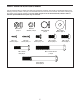
PART IDENTIFICATION CHART Use the drawings below to identify the small parts needed for assembly. The number in parentheses below each drawing is the key number of the part, from the PART LIST near the end of this manual. The number following the key number is the quantity needed for assembly. Note: If a part is not in the hardware kit, check to see if it has been preassembled. Extra parts may be included.
ASSEMBLY • Assembly requires two persons. • In addition to the included tool(s), assembly requires the following tools: • Place all parts in a cleared area and remove the packing materials. Do not dispose of the packing materials until you nish all assembly steps. one Phillips screwdriver one rubber mallet • Left parts are marked “L” or “Left” and right parts are marked “R” or “Right.” Assembly may be easier if you have your own set of wrenches.
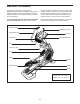
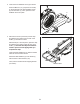
3. Orient the Front Stabilizer Cover (8) as shown. 3 Press the Mounts (117) (only three are shown) on the underside of the Front Stabilizer Cover (8) into the Frame (1). Then, press the Front Stabilizer Cover into place. 8 117 1 4. Remove the screws (not shown) and the shipping bracket (not shown) from the rear of the Frame (1). Discard the screws. 4 With the help of a second person, place the shipping bracket (not shown) under the rear of the Frame (1).
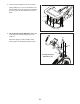
5. Orient the Rear Stabilizer Cover (2) as shown. 5 Press the Mounts (117) on the underside of the Rear Stabilizer Cover (2) into the Rear Stabilizer (5). Then, press the Rear Stabilizer Cover into place. 2 117 5 6. Tip: Avoid pinching the Main Wire (110). Have a second person hold the Upright (4) on the Frame (1). 6 82 Attach the Upright (4) with four M8 x 19mm Screws (82) and four M8 Star Washers (122).
7. Locate the wire tie in the Upright (4). Tie the lower end of the wire tie to the Main Wire (110). Then, pull the upper end of the wire tie until the Main Wire is routed through the Upright. 7 Wire Tie Tip: To prevent the Main Wire (110) from falling into the Upright (4), secure the Main Wire with the wire tie. 4 110 Wire Tie 8. Press the Lower Upright Cover (56) onto the Shield Cover (75).
9. Identify the Left and Right Inner Covers (55, 68) and orient them as shown. 9 55 Slide the Left Inner Cover (55) onto the left side of the Upright (4). Then, slide the Right Inner Cover (68) onto the right side of the Upright. 4 68 10. Using a small plastic bag to keep your fingers clean, apply some of the included grease to the Pivot Axle (35) and to two Wave Washers (95) (only one is shown). 10 4 Insert the Pivot Axle (35) through the Upright (4) and then center it.
11. Tighten an M8 x 16mm Screw (120) and an M8 x 25mm Washer (98) into each end of the Pivot Axle (35) at the same time. 11 120 98 35 98 120 12. Identify the Right Pedal (49) and the Right Pedal Arm (58), and orient them as shown. 12 49 Attach the Right Pedal (49) to the Right Pedal Bracket (139) on the Right Pedal Arm (58) with five M6 x 12mm Screws (121). 58 Repeat this step for the Left Pedal (not shown) and the Left Pedal Arm (not shown).
13. Orient the Left Pedal Arm (44) as shown. 13 Apply grease to the axle on the Left Pedal Arm (44). 44 Attach the Left Pedal Arm (44) to the Left Roller Arm (12) with an M8 x 16mm Screw (120), a Roller Arm Cover (81), and an M8 x 25mm Washer (98). Grease 12 98 Repeat this step for the Right Pedal Arm (not shown). 120 81 14. Tip: Do not slide the Right Upper Body Leg (36) onto the Right Upper Body Arm (61) until step 15. 14 Orient the Right Upper Body Leg (36) as shown.
. Slide the Right Upper Body Leg (36) onto the Right Upper Body Arm (61). 15 Attach the Right Upper Body Leg (36) with two M8 x 35mm Bolts (96) and two M8 Locknuts (102). Make sure that the Locknuts are in the hexagonal holes. 96 Repeat this step on the other side of the elliptical. Hexagonal Holes See step 14. Tighten the M8 x 16mm Screws (120). 36 61 16. Attach the Right Inner Cover (68) to the Right Upper Body Arm (61) with a #8 x 3/4" Screw (123).
17. Untie and discard the wire tie on the Main Wire (110). 17 7 While a second person holds the Console (7) near the Upright (4), connect the wires on the Console to the Main Wire (110), to the Right and Left Grip Wires (41, 48), to the sensor wire (A), and to the Ground Wire (143). 41, 48 Insert the excess wire into the Upright (4) or into the Console (7). 143 A 110 18. Tip: Avoid pinching the wires. Attach the Console (7) to the Upright (4) with four #8 x 1/2" Screws (124).
19. Attach the Rear Upright Cover (80) to the Upright (4) with four #8 x 3/4" Screws (123). 19 123 4 123 80 20. Press the Front Upright Cover (91) onto the Rear Upright Cover (80). 20 123 Attach the Front Upright Cover (91) to the Upright (4) with a #8 x 3/4" Screw (123). 91 4 80 21. Make sure that all parts are properly tightened before you use the elliptical. Note: Extra parts may be included. Place a mat beneath the elliptical to protect the floor.
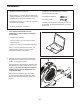
THE CHEST HEART RATE MONITOR HOW TO PUT ON THE HEART RATE MONITOR The heart rate monitor consists of a chest strap and a sensor. Insert the tab on one end of the chest strap into the hole in one end of the sensor as shown. Then, press the end of the sensor under the buckle on the chest strap. The tab should be flush with the front of the sensor.
HOW TO USE THE ELLIPTICAL HOW TO PLUG IN THE POWER CORD A temporary adapter may be used to connect the power cord to a 2-pole receptacle as shown at the right if a properly grounded outlet is not available. This product must be grounded. If it should malfunction or break down, grounding provides a path of least resistance for electric current to reduce the risk of electric shock. The power cord has a plug with a grounding pin.
HOW TO MOVE THE ELLIPTICAL HOW TO EXERCISE ON THE ELLIPTICAL Due to the size and weight of the elliptical, moving it requires two persons. Stand in front of the elliptical, hold the upright, and place one foot against one of the wheels. Pull on the upright and have a second person lift the handle on the ramp until the elliptical will roll on the wheels. Carefully move the elliptical to the desired location, and then lower it to the floor.
CONSOLE DIAGRAM FEATURES OF THE CONSOLE When you use the manual mode of the console, you can change the resistance of the pedals and the incline of the ramp with the touch of a button. The advanced console offers an array of features designed to make your workouts more effective and enjoyable. While you exercise, the console will display continuous exercise feedback. You can also measure your heart rate using the handgrip heart rate monitor or the chest heart rate monitor.
HOW TO TURN ON THE POWER HOW TO USE THE TOUCH SCREEN IMPORTANT: If the elliptical has been exposed to cold temperatures, allow it to warm to room temperature before turning on the power. If you do not do this, you may damage the console displays or other electrical components. The console features a tablet with a full-color touch screen. The following information will help you become familiar with the tablet’s advanced technology: Plug in the power cord (see HOW TO PLUG IN THE POWER CORD on page 19).
HOW TO SET UP THE CONSOLE The Internet browser will open to the iFit.com home page. Touch the Register button in the upper right corner of the screen. Before using the elliptical for the first time, set up the console. The browser will open to the iFit.com registration page. Touch the Buy Now button to register for an iFit account. If you have an activation code, select the code activation option. Then, follow the prompts on the screen to sign up for your iFit membership. 1.
HOW TO USE THE MANUAL MODE on the console, press the Power Ramp increase and decrease buttons on the console, or press the Ramp increase and decrease buttons on the left upper body arm. 1. Touch the screen or press any button on the console to turn on the console. See HOW TO TURN ON THE POWER on page 22. Note: After you press a button, it will take a moment for the ramp to reach the selected incline level. 2. Select the main menu. 4. Follow your progress.
5. Measure your heart rate if desired. Be careful not to move your hands excessively or to squeeze the contacts tightly. For optimal performance, clean the contacts using a soft cloth; never use alcohol, abrasives, or chemicals to clean the contacts. To use the chest heart rate monitor, see page 18. To use the handgrip heart rate monitor, follow the instructions below. IMPORTANT: If you use both heart rate monitors at the same time, the console will not display your heart rate accurately.
HOW TO USE AN ONBOARD WORKOUT If the resistance level and/or incline level for the current segment is too high or too low, you can manually override the setting by pressing the Resistance buttons or the Power Ramp buttons. If you press a Resistance button, you can then manually control the resistance (see step 3 on page 24). If you press a Power Ramp button, you can then manually control the incline (see step 3 on page 24).
HOW TO USE A SET-A-GOAL WORKOUT IMPORTANT: The target rpm is intended only to provide motivation. Your actual pedaling speed may be slower than the target rpm. Make sure to pedal at a speed that is comfortable for you. 1. Begin pedaling or press any button on the console to turn on the console. See HOW TO TURN ON THE POWER on page 22. The workout will continue until you reach the goal that you set. A workout summary will appear on the screen.
HOW TO USE AN IFIT WORKOUT Before some workouts will download, you must add them to your schedule on iFit.com. Note: To use an iFit workout, you must have access to a wireless network (see HOW TO USE THE WIRELESS NETWORK MODE on page 31. An iFit account is also required. For more information about the iFit workouts, please see www.iFit.com. When you select an iFit workout, the screen will show the name, duration, and distance of the workout.
HOW TO USE THE EQUIPMENT SETTINGS MODE passcode of your choice. Touch Save to use this passcode. Touch Cancel to return to the equipment settings mode and not use a passcode. To disable the passcode, touch the Disable checkbox. 1. Select the settings main menu. Turn on the console and select the main menu (see steps 1 and 2 on page 24). Then, touch the gears button at the bottom of the screen to select the settings main menu.
HOW TO USE THE MAINTENANCE MODE incline level, lower to the minimum incline level, and then return to the starting position. This will calibrate the incline. Press the Cancel button to return to the maintenance mode. When the incline is calibrated, touch the Finish button. 1. Select the settings main menu. See step 1 on page 29. 2. Select the maintenance mode. IMPORTANT: Keep pets, feet, and other objects away from the elliptical while the incline is calibrating.
HOW TO USE THE WIRELESS NETWORK MODE name (SSID). If your network has a password, you will also need to know the password. The console features a wireless network mode that allows you to set up a wireless network connection. An information box will ask if you want to connect to the wireless network. Touch the Connect button to connect to the network or touch the Cancel button to return to the list of networks. If the network has a password, touch the password entry box.
HOW TO USE THE SOUND SYSTEM HOW TO USE THE INTERNET BROWSER To play music or audio books through the console sound system, you must connect your MP3 player, CD player, or other personal audio player to the console. Note: To use the Internet browser, you must have access to a wireless network including a wireless router (802.11b/g/n) with SSID broadcast enabled (hidden networks are not supported). Plug one end of your audio wire into the audio jack on the console.
FCC INFORMATION This equipment has been tested and found to comply with the limits for a Class B digital device, pursuant to part 15C of the FCC Rules. These limits are designed to provide reasonable protection against harmful interference in a residential installation. This equipment generates, uses, and can radiate radio frequency energy and, if not installed and used in accordance with the instructions, may cause harmful interference to radio communications.
MAINTENANCE AND TROUBLESHOOTING Inspect and tighten all parts of the elliptical regularly. Replace any worn parts immediately. To adjust the drive belt, first use a flat screwdriver to remove the Lower Upright Cover (56). To clean the elliptical, use a damp cloth and a small amount of mild soap. IMPORTANT: To avoid damage to the console, keep liquids away from the console and keep the console out of direct sunlight.
Loosen the M6 x 12mm Hex Screw (85) and the M10 x 58mm Hex Bolt (86). Then, remove the right Crank Arm (20). Gently move the right Crank Arm and the Right Roller Arm (45) out of the way. Do not misplace the Key (78) while removing the Crank Arm. HOW TO ADJUST THE REED SWITCH If the console does not display correct feedback, the reed switch should be adjusted. 86 78 85 To adjust the reed switch, first remove the three M4 x 16mm Screws (104) and the M4 x 16mm Machine Screw (128) from the left Disc (71).
EXERCISE GUIDELINES Burning Fat—To burn fat effectively, you must exercise at a low intensity level for a sustained period of time. During the first few minutes of exercise, your body uses carbohydrate calories for energy. Only after the first few minutes of exercise does your body begin to use stored fat calories for energy. If your goal is to burn fat, adjust the intensity of your exercise until your heart rate is near the lowest number in your training zone.
SUGGESTED STRETCHES The correct form for several basic stretches is shown at the right. Move slowly as you stretch; never bounce. 1. Toe Touch Stretch Stand with your knees bent slightly and slowly bend forward from your hips. Allow your back and shoulders to relax as you reach down toward your toes as far as possible. Hold for 15 counts, then relax. Repeat 3 times. Stretches: Hamstrings, back of knees and back. 1 2. Hamstring Stretch Sit with one leg extended.
PART LIST Key No. Qty. 1 2 3 4 5 6 7 8 9 10 11 12 13 14 15 16 17 18 19 20 21 22 23 24 25 26 27 28 29 30 31 32 33 34 35 36 37 38 39 40 41 42 43 44 45 46 47 48 49 50 1 1 1 1 1 1 1 1 1 1 2 1 1 1 1 1 1 1 1 2 2 1 4 4 1 2 2 1 1 6 1 2 2 2 1 1 1 1 1 2 1 1 2 1 1 1 1 1 1 2 Model No. NTEL21412.2 R0513A Description Key No. Qty.
Key No. Qty. 101 102 103 104 105 106 107 108 109 110 111 112 113 114 115 116 117 118 119 120 121 122 123 124 125 126 127 1 10 2 44 4 3 4 2 1 1 1 1 1 1 4 2 30 1 2 14 10 4 11 4 2 2 14 Description Key No. Qty.
79 40 120 66 64 121 94 29 121 103 123 100 104 137 137 104 21 99 57 136 70 59 98 98 96 120 120 53 138 121 90 14 44 54 47 126 59 46 53 102 95 57 81 120 104 98 137 99 135 90 137 123 76 104 80 104 123 35 133 12 53 120 120 55 37 51 98 33 104 70 104 48 104 128 133 71 104 104 91 104 104 104 52 140 75 104 73 104 60 104 128 93 56 24 23 114 93 26 104 23 EXPLODED DRAWING A Model No. NTEL21412.
104 62 105 50 92 5 119 113 20 78 86 85 98 105 15 32 104 62 120 129 98 72 30 108 125 28 104 40 107 42 102 145 99 104 38 92 132 108 31 27 98 30 120 72 65 39 97 13 145 102 32 22 27 125 118 129 30 105 88 89 106 104 25 109 101 93 106 17 92 16 132 104 1 6 34 83 102 43 102 40 116 18 43 142 99 141 85 86 141 144 142 19 92 116 34 84 50 78 20 105 98 99 EXPLODED DRAWING B Model No. NTEL21412.
104 127 42 126 104 127 77 127 104 104 104 21 81 128 127 98 104 127 104 33 51 120 74 57 60 57 104 71 111 137 100 79 104 64 139 104 133 90 45 137 128 99 53 121 120 98 133 104 135 123 68 94 87 58 49 120 137 137 99 90 120 61 104 104 104 96 70 103 95 41 104 53 70 98 59 59 36 102 120 53 136 120 98 123 67 EXPLODED DRAWING C Model No. NTEL21412.
115 93 117 3 79 43 127 79 134 115 11 115 117 127 117 93 10 9 117 127 115 117 117 79 79 7 117 2 110 124 117 117 8 104 117 4 69 30 117 124 117 123 123 63 130 112 82 104 122 143 30 131 106 EXPLODED DRAWING D Model No. NTEL21412.
ORDERING REPLACEMENT PARTS To order replacement parts, please see the front cover of this manual.