nordictrack.com Model No. NTEX02121.2 Serial No. Write the serial number in the space above for reference. Serial Number Decal ACTIVATE YOUR WARRANTY To register your product and activate your warranty today, go to my.nordictrack.com. CUSTOMER CARE For service at any time, go to support.nordictrack.com. Or call 1-800-TO-BE-FIT (1-800-862-3348) Mon.–Fri. 6 a.m.–6 p.m. MT Sat. 8 a.m.–12 p.m. MT Please do not contact the store.
TABLE OF CONTENTS WARNING DECAL PLACEMENT . . . . . . . . . . . . . . . . . . . . . . . . . . . . . . . . . . . . . . . . . . . . . . . . . . . . . . . . . . . . . . .2 IMPORTANT PRECAUTIONS. . . . . . . . . . . . . . . . . . . . . . . . . . . . . . . . . . . . . . . . . . . . . . . . . . . . . . . . . . . . . . . . . . 3 BEFORE YOU BEGIN. . . . . . . . . . . . . . . . . . . . . . . . . . . . . . . . . . . . . . . . . . . . . . . . . . . . . . . . . . . . . . . . . . . . . . . .5 PART IDENTIFICATION CHART.
IMPORTANT PRECAUTIONS WARNING: To reduce the risk of serious injury, read all important precautions and instructions in this manual and all warnings on your studio cycle before using your studio cycle. ICON assumes no responsibility for personal injury or property damage sustained by or through the use of this product. 1. It is the responsibility of the owner to ensure that all users of the studio cycle are adequately informed of all precautions. 9.
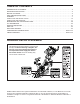
STANDARD SERVICE PLANS 4
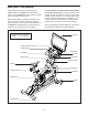
BEFORE YOU BEGIN For your benefit, read this manual carefully before you use the studio cycle. If you have questions after reading this manual, please see the front cover of this manual. To help us assist you, note the product model number and serial number before contacting us. The model number and the location of the serial number decal are shown on the front cover of this manual. Congratulations for selecting the revolutionary NORDICTRACK® COMMERCIAL S22I STUDIO CYCLE.
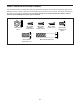
PART IDENTIFICATION CHART Use the drawings below to identify the small parts needed for assembly. The number in parentheses below each drawing is the key number of the part, from the PART LIST near the end of this manual. The number following the key number is the quantity needed for assembly. Note: If a part is not in the hardware kit, check to see if it has been preassembled. Extra parts may be included.
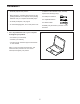
ASSEMBLY • Assembly requires two persons. • In addition to the included tool(s), assembly requires the following tool(s): • Place all parts in a cleared area and remove the packing materials. Do not dispose of the packing materials until you complete all assembly steps. one Phillips screwdriver one adjustable wrench • To identify small parts, see page 6. one rubber mallet • To avoid damaging parts, do not use power tools. Assembly may be easier if you have a set of wrenches. 1. Go to my.
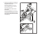
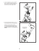
2. Attach the Front Stabilizer (3) to the Base (2) with four M10 x 20mm Screws (105); do not fully tighten the Screws yet. 2 See the inset drawing. Finish attaching the Front Stabilizer (3) with two additional M10 x 20mm Screws (105). 105 Then, fully tighten all six M10 x 20mm Screws (105). 105 See the inset drawing. Press the right Leg Cover (64) downward and attach it to the Base (2) with an M4 x 10mm Machine Screw (12). Then, attach the left Leg Cover (not shown) in the same way.
3. Attach the Rear Stabilizer (4) to the Base (2) with four M10 x 20mm Screws (105); do not fully tighten the Screws yet. 3 105 105 See the inset drawing. Finish attaching the Rear Stabilizer (4) with two additional M10 x 20mm Screws (105). Then, fully tighten all six M10 x 20mm Screws (105). 2 4 105 105 4 4. See the inset drawing. Orient the Handlebar Post (7) so that the lower slot (A) is on the side shown.
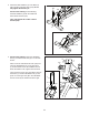
5. Insert the Handlebar (97) into the Handlebar Post (7). Attach the Handlebar with four M8 x 12mm Patch Screws (93); start all the Patch Screws, and then tighten them. 5 97 7 93 6. Tip: Avoid pinching the wires (C). Slide the Console Support (8) onto the Handlebar (97). 93 6 Attach the Console Support (8) with an M10 x 52mm Bolt (94) and an M10 Jam Nut (95); make sure that the Jam Nut is in the hexagonal hole (D). Do not fully tighten the Bolt yet.
7. Look under the Console Support (8) and identify the Upper Wire (123), which has a larger connector than the Extension Wire (124). 7 Connect the Upper Wire (123) to the Lower Wire (122) extending from the Handlebar Post (7). Then, insert the connectors on both Wires into the Handlebar Post. 8 Next, connect the Extension Wire (124) to the Control Wire (125) extending from the Handlebar (97). Then, insert the connectors on both Wires into the Handlebar. 97 125 123 124 7 122 8.
9. IMPORTANT: Have a second person move the Console (10) from side to side, if necessary, so that it is level. While the second person holds the Console still, firmly tighten the M10 x 52mm Bolt (94). 9 10 Avoid pinching the wires (C) Next, orient the Hand Weight Tray (38) so that the orientation sticker (F) is in the location shown. F 38 Tip: Avoid pinching the wires (C).
11. Note: You can attach your own saddle if desired. 11 54 See inset drawing a. Tip the Saddle (54) to one side and slide one of the rails (G) as far as possible between the Lower Saddle Clamp (52) and the Upper Saddle Clamp (53). If necessary, further loosen the M8 Saddle Screw (41). G 53 52 See inset drawing b. Tip the Saddle (54) downward as shown and slide the other rail (G) between the Saddle Clamps (52, 53).
13. Set the two Hand Weights (14) in the Hand Weight Tray (38). 13 IMPORTANT: Make sure not to hit the Console (10) with the Hand Weights (14) when you set the Hand Weights in the Hand Weight Tray (38) after each use. 10 14 38 14. IMPORTANT: Always plug the Power Adapter (119) into the studio cycle before you plug it into an outlet. 14 Route the Power Adapter (119) through the two Anchored Zip Ties (55) on the Base (2).
HOW TO USE THE STUDIO CYCLE HOW TO PLUG IN THE POWER ADAPTER Interactive Wireless Touchscreen Console IMPORTANT: If the studio cycle has been exposed to cold temperatures, allow it to warm to room temperature before you plug in the power adapter (A). If you do not do this, you may damage the console displays or other electronic components.
How to Adjust the Saddle Post HOW TO LEVEL THE STUDIO CYCLE For effective training, the saddle should be at the proper height. As you pedal, there should be a slight bend in your knees when the pedals are in the lowest position. If the studio cycle rocks slightly on your floor during use, turn one or both of the leveling feet (G ) beneath the rear stabilizer until the rocking motion is eliminated.
HOW TO USE THE CONSOLE CONSOLE DIAGRAM FEATURES OF THE CONSOLE When you use the manual mode of the console, you can change the resistance of the pedals and the incline of the frame with the touch of a button. The advanced console offers an array of features designed to make your workouts more effective and enjoyable. While you exercise, the console will display continuous exercise feedback. You can even measure your heart rate using a compatible heart rate monitor.
HOW TO TURN ON THE CONSOLE HOW TO USE THE TOUCH SCREEN The included power adapter must be used to operate the studio cycle. See HOW TO PLUG IN THE POWER ADAPTER on page 15. When the power adapter is plugged in, touch the screen or press any button on the console to turn on the console. The console features a tablet with a full-color touch screen. The following information will help you use the touch screen: • The console functions similarly to other tablets.
HOW TO SET UP THE CONSOLE then touch Calibrate Incline. The frame will rise and lower as it calibrates. For more information, see HOW TO CHANGE CONSOLE SETTINGS on page 25. Before you use the studio cycle for the first time, set up the console. 1. Connect to your wireless network. The console is now ready for you to begin working out. The following pages explain the workouts and other features that the console offers.
3. Change the resistance of the pedals and the incline of the frame as desired. 5. Wear a compatible heart rate monitor and measure your heart rate if desired. Touch Manual Start and begin pedaling. You can wear a compatible heart rate monitor to measure your heart rate. Note: The console is compatible with all Bluetooth® Smart heart rate monitors. You can change the resistance of the pedals by pressing the Resistance increase and decrease buttons on the right handlebar.
HOW TO USE A FEATURED WORKOUT To draw your own map for a workout, see HOW TO CREATE A DRAW-YOUR-OWN-MAP WORKOUT on page 23. 1. Touch the screen or press any button on the console to turn on the console. When you select a workout, the screen will show an overview of the workout that includes details such as the duration and distance of the workout and the approximate number of calories you will burn during the workout. See HOW TO TURN ON THE CONSOLE on page 18.
If the resistance level and/or incline level is too high or too low, you can manually override the setting by pressing the Resistance buttons or the Incline/ Decline buttons. If you press a Resistance button, you can then manually control the resistance level (see step 3 on page 20). If you press an Incline/Decline button, you can then manually control the incline level (see step 3 on page 20). To return to the programmed resistance and/or incline settings of the workout, touch Follow Workout.
HOW TO CREATE A DRAW-YOUR-OWN-MAP WORKOUT If you make a mistake, touch Undo in the map options. 1. Touch the screen or press any button on the console to turn on the console. The screen will display the elevation and distance statistics for your workout. See HOW TO TURN ON THE CONSOLE on page 18. Note: It may take a few moments for the console to be ready for use. 4. Save your workout. Touch Save New Workout to save your workout. If desired, enter a title and description for your workout.
HOW TO USE AN IFIT WORKOUT associated with the account, a list of users will appear. Touch the name of the desired user. To use an iFit workout, the console must be connected to a wireless network (see HOW TO CONNECT TO A WIRELESS NETWORK on page 26). An iFit account is also required. 4. Select an iFit workout that you have previously added to your schedule on iFit.com. IMPORTANT: Before iFit workouts will load, you must add them to your schedule on iFit.com (see step 1). 1.
HOW TO CHANGE CONSOLE SETTINGS 3. Customize workout settings. IMPORTANT: Some of the settings and features described may not be enabled. Occasionally, a firmware update may cause your console to function slightly differently. To customize workout settings, touch In Workout, and then touch the desired settings. It is recommended that you enable the option to show slider controls on the screen, if available. 1. Select the settings main menu. 4. Customize the unit of measurement and other settings.
7. Calibrate the incline system. 3. Enable Wi-Fi. To calibrate the incline system, touch Maintenance, touch Calibrate Incline, and then touch Begin. The frame will automatically rise to the maximum incline level, lower to the minimum incline level, and then return to the starting position. This will calibrate the incline system. When the incline system is calibrated, touch Finish. Make sure that Wi-Fi® is enabled. If it is not enabled, touch the Wi-Fi toggle to enable it. 4.
HOW TO USE THE SOUND SYSTEM Connect Your Headphones If the console has a headphones jack, you can plug your headphones into the headphones jack to listen to audio from the console through your headphones. Connect with an Audio Cable To play music or audio books through the console sound system while you exercise, plug a 3.5 mm male to 3.
MAINTENANCE AND TROUBLESHOOTING MAINTENANCE If the console does not boot up properly, or if the console freezes and does not respond, reset the console A to the factory default settings. IMPORTANT: Doing this will erase all custom settings you have made to the console. Resetting the console requires two people. First, unplug the power adapter. Next, locate the small reset opening (A) on the side or the back of the console.
HOW TO ADJUST THE LEFT CRANK ARM HOW TO ADJUST THE REED SWITCH If the Left Crank Arm (21) feels loose while you are pedaling, first loosen the two M6 x 25mm Screws (96). Then, follow the steps below. Note: If you have a torque wrench, tighten the Screws (15, 96) to the listed torque specs. If you do not have a torque wrench, simply tighten the Screws as firmly as you can. If the console does not display correct feedback, the reed switch should be adjusted.
HOW TO ADJUST THE DRIVE BELT If you can feel the pedals slip while you are pedaling, even when the resistance is adjusted to the highest setting, the drive belt may need to be adjusted. 31 To adjust the drive belt, first unplug the power adapter. Then, follow the instructions below. Note: The drawings show only the right side of the studio cycle. 152 Remove the indicated #8 x 5/8" Screw (152) and the Shield Cover (31) from each side of the studio cycle.
EXERCISE GUIDELINES Aerobic Exercise—If your goal is to strengthen your cardiovascular system, you must perform aerobic exercise, which is activity that requires large amounts of oxygen for prolonged periods of time. For aerobic exercise, adjust the intensity of your exercise until your heart rate is near the highest number in your training zone. WARNING: Before beginning this or any exercise program, consult your physician.
PART LIST Key No. Qty. 1 2 3 4 5 6 7 8 9 10 11 12 13 14 15 16 17 18 19 20 21 22 23 24 25 26 27 28 29 30 31 32 33 34 35 36 37 38 39 40 41 42 43 44 45 46 47 48 49 50 1 1 1 1 1 2 1 1 1 1 1 2 1 2 1 1 4 4 1 1 1 1 1 2 1 2 2 2 1 1 2 1 1 1 1 1 1 1 1 1 1 1 2 3 1 1 1 1 2 1 Model No. NTEX02121.2 R1020A Description Key No. Qty.
Key No. Qty. 101 102 103 104 105 106 107 108 109 110 111 112 113 114 115 116 117 118 119 120 121 122 123 124 125 126 127 128 1 4 4 2 12 1 2 3 1 2 2 1 2 2 1 1 1 1 1 1 1 1 1 1 1 2 8 2 Description Key No. Qty.
EXPLODED DRAWING A 129 126 127 130 51 60 66 Model No. NTEX02121.
EXPLODED DRAWING B Model No. NTEX02121.
ORDERING REPLACEMENT PARTS To order replacement parts, please see the front cover of this manual.