nordictrack.com Model No. NTEX05117.0 Serial No. Write the serial number in the space above for reference. Serial Number Decal ACTIVATE YOUR WARRANTY To register your product and activate your warranty today, go to my.nordictrack.com. CUSTOMER CARE For service at any time, go to nordictrackservice.com. Or call 1-800-TO-BE-FIT (1-800-862-3348) Mon.–Fri. 6 a.m.–6 p.m. MT Sat. 8 a.m.–12 p.m. MT Please do not contact the store.
TABLE OF CONTENTS WARNING DECAL PLACEMENT . . . . . . . . . . . . . . . . . . . . . . . . . . . . . . . . . . . . . . . . . . . . . . . . . . . . . . . . . . . . . . .2 IMPORTANT PRECAUTIONS. . . . . . . . . . . . . . . . . . . . . . . . . . . . . . . . . . . . . . . . . . . . . . . . . . . . . . . . . . . . . . . . . . 3 BEFORE YOU BEGIN. . . . . . . . . . . . . . . . . . . . . . . . . . . . . . . . . . . . . . . . . . . . . . . . . . . . . . . . . . . . . . . . . . . . . . . .6 PART IDENTIFICATION CHART.
IMPORTANT PRECAUTIONS WARNING: To reduce the risk of burns, fire, electric shock, or injury to persons, read all important precautions and instructions in this manual and all warnings on your studio cycle before using your studio cycle. ICON assumes no responsibility for personal injury or property damage sustained by or through the use of this product. 1. It is the responsibility of the owner to ensure that all users of the studio cycle are adequately informed of all precautions. 8.
15. The studio cycle should not be used by persons weighing more than 350 lbs. (159 kg). flywheel stops. Reduce your pedaling speed in a controlled way. 19. To stop the flywheel quickly, press the brake knob downward. 16. Be careful when mounting and dismounting the studio cycle. 20. Over exercising may result in serious injury or death. If you feel faint, if you become short of breath, or if you experience pain while exercising, stop immediately and cool down. 17.
STANDARD SERVICE PLANS 5
BEFORE YOU BEGIN For your benefit, read this manual carefully before you use the studio cycle. If you have questions after reading this manual, please see the front cover of this manual. To help us assist you, note the product model number and serial number before contacting us. The model number and the location of the serial number decal are shown on the front cover of this manual. Congratulations for selecting the revolutionary NORDICTRACK® COMMERCIAL S10I STUDIO CYCLE.
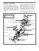
PART IDENTIFICATION CHART Use the drawings below to identify the small parts needed for assembly. The number in parentheses below each drawing is the key number of the part, from the PART LIST near the end of this manual. The number following the key number is the quantity needed for assembly. Note: If a part is not in the hardware kit, check to see if it has been preassembled. Extra parts may be included.
ASSEMBLY • Assembly requires two persons. • In addition to the included tool(s), assembly requires the following tool(s): • Place all parts in a cleared area and remove the packing materials. Do not dispose of the packing materials until you complete all assembly steps. one Phillips screwdriver one adjustable wrench • To identify small parts, see page 7. one rubber mallet • To avoid damaging parts, do not use power tools. Assembly may be easier if you have a set of wrenches. 1. Go to my.
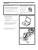
3. Attach the Front Stabilizer (3) to the Base (2) with two M10 x 20mm Screws (105). 3 105 2 3 4. See the inset drawing. Orient the Handlebar Post (7) so that the lower slot (A) is on the side shown. 4 B 7 100 Next, loosen the indicated Post Knob (100) and insert the Handlebar Post (7) into the Frame (1) until the lower end of the Handlebar Post is below the Frame. Then, tighten the Post Knob.
5. Insert the Handlebar (97) into the Handlebar Post (7). Attach the Handlebar with four M8 x 12mm Screws (93); start all the Screws, and then tighten them. 5 97 7 93 6. Tip: Avoid pinching the wires (C). Slide the Console Support (8) onto the Handlebar (97). 93 6 Attach the Console Support (8) with an M10 x 52mm Bolt (94) and an M10 Jam Nut (95); make sure that the Jam Nut is in the hexagonal hole (D). Do not fully tighten the Bolt yet.
7. Look under the Console Support (8) and identify the Upper Wire (123), which has a larger connector than the Extension Wire (124). 7 Connect the Upper Wire (123) to the Lower Wire (122) extending from the Handlebar Post (7). Then, insert the connectors on both Wires into the Handlebar Post. 8 Next, connect the Extension Wire (124) to the Control Wire (125) extending from the Handlebar (97). Then, insert the connectors on both Wires into the Handlebar. 8.
9. Have a second person hold the Console (10) near the Console Bracket (11). 9 Plug the Upper Wire (123) and the Extension Wire (124) into the receptacles on the back of the Console (10); make sure to plug the Wire marked with red into the receptacle marked with red, and plug the Wire marked with yellow into the receptacle marked with yellow. 11 102 10 102 123 Tip: Avoid pinching the wires. If necessary, tilt the Console Bracket (11) upward to make this step easier.
11. Orient the Saddle Post (13) as shown. 11 Loosen the indicated Post Knob (100). Next, insert the Saddle Post (13) into the Frame (1), and slide the Saddle Post to the desired height. Then, tighten the Post Knob. 13 100 1 12. Note: You can attach your own saddle if desired. 12 54 See inset drawing a. Tip the Saddle (54) to one side and slide one of the rails (F) as far as possible between the Lower Saddle Clamp (52) and the Upper Saddle Clamp (53).
13. Note: You can attach your own pedals if desired. 13 Identify the right Pedal (56). Using an adjustable wrench, firmly tighten the right Pedal clockwise into the Right Crank Arm (19). Firmly tighten the left Pedal (not shown) counterclockwise into the Left Crank Arm (not shown). IMPORTANT: You must turn the left Pedal counterclockwise to attach it. 19 56 14. Set the two Hand Weights (14) in the Hand Weight Tray (38).
HOW TO USE THE STUDIO CYCLE HOW TO PLUG IN THE POWER CORD A temporary adapter may be used to connect the power cord to a 2-pole receptacle as shown at the right if a properly grounded outlet is not available. This product must be grounded. If it should malfunction or break down, grounding provides a path of least resistance for electric current to reduce the risk of electric shock. The power cord has a plug with a grounding pin.
FEATURES OF THE STUDIO CYCLE HOW TO ADJUST THE GEOMETRY OF THE STUDIO CYCLE Measuring Watts The studio cycle can be adjusted to match the geometry of your road bike to promote correct form and to ensure proper training of the muscles. Make adjustments in small increments, and then pedal the studio cycle to test the adjustments. Each studio cycle is calibrated to measure your power output and to allow you to monitor your watts and RPMs directly on the console.
How to Adjust the Saddle Post HOW TO LEVEL THE STUDIO CYCLE For effective training, the saddle should be at the proper height. As you pedal, there should be a slight bend in your knees when the pedals are in the lowest position. If the studio cycle rocks slightly on your floor during use, turn one or both of the leveling feet (F) beneath the rear stabilizer until the rocking motion is eliminated.
CONSOLE DIAGRAM FEATURES OF THE CONSOLE When you use the manual mode of the console, you can change the resistance of the pedals and the incline of the frame with the touch of a button. The advanced console offers an array of features designed to make your workouts more effective and enjoyable. While you exercise, the console will display continuous exercise feedback. You can also measure your heart rate using an optional chest heart rate monitor (see page 28 for more information).
HOW TO TURN ON THE POWER HOW TO USE THE TOUCH SCREEN IMPORTANT: If the studio cycle has been exposed to cold temperatures, allow it to warm to room temperature before you turn on the power. If you do not do this, you may damage the console or other electrical components. The console features a tablet with a full-color touch screen. The following information will help you use the touch screen: Plug in the power cord (see HOW TO PLUG IN THE POWER CORD on page 15).
HOW TO SET UP THE CONSOLE 5. Check for firmware updates. Before you use the studio cycle for the first time, set up the console. First, touch the profile button, touch Settings, touch Maintenance, and then touch Update. The console will check for firmware updates. For more information, see HOW TO CHANGE CONSOLE SETTINGS on page 25. 1. Connect to your wireless network. To use iFit workouts and to use several other features of the console, the console must be connected to a wireless network.
HOW TO USE THE MANUAL MODE If desired, adjust the volume level by pressing the volume increase and decrease buttons on the right side of the console. 1. Touch the screen or press any button on the console to turn on the console. To pause the workout, simply touch the screen or stop pedaling. To continue the workout, simply resume pedaling. See HOW TO TURN ON THE POWER on page 19. Note: It may take a few moments for the console to be ready for use.
HOW TO USE A MAP WORKOUT OR AN ONBOARD WORKOUT To draw your own map for a workout, see HOW TO CREATE A DRAW-YOUR-OWN-MAP WORKOUT on page 23. 1. Touch the screen or press any button on the console to turn on the console. See HOW TO TURN ON THE POWER on page 19. Note: It may take a few moments for the console to be ready for use.
If the resistance level and/or incline level is too high or too low, you can manually override the setting by pressing the Resistance buttons or the Incline/ Decline buttons. If you press a Resistance button, you can then manually control the resistance level (see step 3 on page 21). If you press an Incline/Decline button, you can then manually control the incline level (see step 3 on page 21). To return to the programmed resistance and/ or incline settings of the workout, touch Follow Workout.
4. Save your workout. HOW TO USE AN IFIT WORKOUT Touch Save New Workout to save your workout. If desired, enter a title and description for your workout. Then, touch the continue button (> symbol). To use an iFit workout, the console must be connected to a wireless network (see HOW TO CONNECT TO A WIRELESS NETWORK on page 27). An iFit account is also required. 5. Start the workout. 1. Add workouts to your schedule on iFit.com. Touch Start to start the workout.
4. Select an iFit workout that you have previously added to your schedule on iFit.com. HOW TO CHANGE CONSOLE SETTINGS IMPORTANT: Some of the settings and features described may not be enabled. Occasionally, a firmware update may cause your console to function slightly differently. IMPORTANT: Before iFit workouts will load, you must add them to your schedule on iFit.com (see step 1). 1. Select the settings main menu. To load an iFit workout from iFit.
3. View the console tour presentation. The screen will show the progress of the update. When the update is complete, the studio cycle will turn off and then turn back on. If it does not, press the power switch into the off position. Wait for several seconds, and then press the power switch into the reset position. Note: It may take a few minutes for the console to be ready for use. To view a tour presentation that will guide you through the features of the console, touch How It Works. 4.
HOW TO CONNECT TO A WIRELESS NETWORK Follow the prompts on the screen to enter your password and connect to the selected wireless network. (To use the keyboard, see HOW TO USE THE TOUCH SCREEN on page 19.) To use iFit workouts and to use several other features of the console, the console must be connected to a wireless network. When the console is connected to your wireless network, a checkmark will appear next to the wireless network name. 1. Select the main menu.
HOW TO CONNECT AN HDMI CABLE enable you to continuously monitor your heart rate while you exercise, helping you to reach your personal fitness goals. To purchase a chest heart rate monitor, please see the front cover of this manual. To show your console screen on a TV or monitor, plug an HDMI cable (not included) into the port on the console and into a port on your TV or monitor; make sure that the HDMI cable is fully plugged in. Note: To purchase an HDMI cable, see your local electronics store.
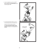
MAINTENANCE AND TROUBLESHOOTING MAINTENANCE HOW TO ADJUST THE LEFT CRANK ARM Regular maintenance is important for optimal performance and to reduce wear. Inspect and properly tighten all parts each time the studio cycle is used. Replace any worn parts immediately. If the Left Crank Arm (21) feels loose while you are pedaling, tighten the two M6 x 25mm Screws (96). 96 To clean the studio cycle, use a damp cloth and a small amount of mild soap.
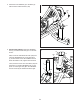
Next, remove all of the Screws (not shown) attaching the Right and Left Shields (30, 32); make sure to remember where the two shortest Screws are located. Then, move the Left Shield out of the way until you can reach the Reed Switch (115). Remove the indicated M4 x 16mm Screw (83) and the Shield Cover (31) from each side of the studio cycle. 31 83 30, 32 115 137 83 27 26 Slightly loosen the two M4 x 16mm Screws (83).
EXERCISE GUIDELINES Aerobic Exercise—If your goal is to strengthen your cardiovascular system, you must perform aerobic exercise, which is activity that requires large amounts of oxygen for prolonged periods of time. For aerobic exercise, adjust the intensity of your exercise until your heart rate is near the highest number in your training zone. WARNING: Before beginning this or any exercise program, consult your physician.
PART LIST Key No. Qty. 1 2 3 4 5 6 7 8 9 10 11 12 13 14 15 16 17 18 19 20 21 22 23 24 25 26 27 28 29 30 31 32 33 34 35 36 37 38 39 40 41 42 43 44 45 46 47 48 49 50 1 1 1 1 1 2 1 1 1 1 1 6 1 2 1 1 4 4 1 1 1 1 1 2 1 2 2 2 1 1 2 1 1 1 1 1 1 1 1 1 1 1 2 3 1 1 1 1 2 1 Model No. NTEX05117.0 R0118A Description Key No. Qty.
Key No. Qty. 101 102 103 104 105 106 107 108 109 110 111 112 113 114 115 116 117 118 119 120 121 122 123 124 125 126 1 4 2 4 4 1 2 3 1 2 2 1 2 2 1 1 1 1 1 1 1 1 1 1 1 6 Description Key No. Qty.
EXPLODED DRAWING A 126 129 127 130 51 60 92 50 128 83 40 103 91 90 58 62 127 69 68 85 115 83 59 127 126 100 5 60 65 55 83 12 140 108 103 66 12 1 66 58 127 63 24 9 20 118 27 79 24 44 59 127 105 126 68 64 12 87 49 49 3 99 108 138 98 120 83 83 83 78 76 34 64 29 83 83 4 69 6 44 88 34 83 121 69 2 105 80 104 75 138 108 89 150 62 119 44 74 117 36 149 126 26 148 147 81 22 35 144 143 82 83 143 126 84 63 69 142 145 146 126 116 2
EXPLODED DRAWING B Model No. NTEX05117.
ORDERING REPLACEMENT PARTS To order replacement parts, please see the front cover of this manual.