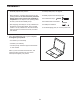
nordictrack.com USER’S MANUAL Model No. NTL39019.0 Serial No. Write the serial number in the space above for reference. Serial Number Decal ACTIVATE YOUR WARRANTY To register your product and activate your warranty today, go to my.nordictrack.com CUSTOMER CARE For service at any time, go to nordictrackservice.com. Or call 1-800-TO-BE-FIT (1-800-862-3348) Mon.–Fri. 6 a.m.–6 p.m. MT Sat. 8 a.m.–12 p.m. MT Please do not contact the store.
TABLE OF CONTENTS WARNING DECAL PLACEMENT . . . . . . . . . . . . . . . . . . . . . . . . . . . . . . . . . . . . . . . . . . . . . . . . . . . . . . . . . . . . . . . 2 IMPORTANT PRECAUTIONS . . . . . . . . . . . . . . . . . . . . . . . . . . . . . . . . . . . . . . . . . . . . . . . . . . . . . . . . . . . . . . . . . . 3 BEFORE YOU BEGIN. . . . . . . . . . . . . . . . . . . . . . . . . . . . . . . . . . . . . . . . . . . . . . . . . . . . . . . . . . . . . . . . . . . . . . . .
IMPORTANT PRECAUTIONS WARNING: To reduce the risk of burns, fire, electric shock, or injury to persons, read all important precautions and instructions in this manual and all warnings on your incline trainer before using your incline trainer. ICON assumes no responsibility for personal injury or property damage sustained by or through the use of this product. 1. It is the responsibility of the owner to ensure that all users of this incline trainer are adequately informed of all warnings and precautions.
the power switch), and unplug the power cord when the incline trainer is not in use. 18. Read, understand, and test the emergency stop procedure before using the incline trainer. (See HOW TO TURN ON THE POWER on page 18.) Always wear the clip while using the incline trainer. 25. Do not attempt to move the incline trainer until it is properly assembled. (See ASSEMBLY on page 9, and HOW TO MOVE THE INCLINE TRAINER on page 28.) You must be able to safely lift 45 lbs.
STANDARD SERVICE PLANS all 6
BEFORE YOU BEGIN Thank you for selecting the revolutionary NORDICTRACK® COMMERCIAL X32I. The COMMERCIAL X32I offers a selection of features designed to make your workouts at home more effective and enjoyable. reading this manual, please see the front cover of this manual. To help us assist you, note the product model number and serial number before contacting us. The model number and the location of the serial number decal are shown on the front cover of this manual.
PART IDENTIFICATION CHART Use the drawings below to identify small parts used for assembly. The number in parentheses below each drawing is the key number of the part, from the PART LIST near the end of this manual. The number following the key number is the quantity used for assembly. Note: If a part is not in the hardware kit, check to see whether it is preattached. Extra parts may be included.
ASSEMBLY • Assembly requires two persons. • To identify small parts, see page 8. • Place all parts in a cleared area and remove the packing materials. Do not remove the protective plastic sheet on the console until assembly is completed. Do not dispose of the packing materials until you finish all assembly steps. • Assembly requires the following tools: the included hex keys the included offset screwdriver • After shipping, there may be an oily substance on the exterior of the incline trainer.
2. Make sure that the power cord is unplugged. 2 Remove the four 3/8" x 3 1/4" Screws (18) from the Base (74) (only one side is shown). Save the Screws. 18 74 3. Remove the four 3/8" x 2 3/4" Screws (22) from the Uprights (83). Save the Screws.
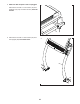
4. Set the Uprights (83) on the Base (74). Make sure that the hole with the Upright Wire (75) is on the right side. 4 Attach the right Upright (83) with two of the 3/8" x 3 1/4" Screws (18) and two of the 3/8" x 2 3/4" Screws (22) that you just removed and four 3/8" Star Washers (3); do not fully tighten the Screws yet. Make sure that the Base Wire (52) is not pinched. 83 Attach the left Upright (not shown) as described above. Note: There is not a wire on the left side.
6. Identify the right handrail assembly (C). With the help of a second person, set the right handrail assembly on the console assembly (D). Note: See the inset drawing. Tip the top of the handrail slightly to the right as you set the handrail on the console assembly. 6 Attach the right handrail assembly (C) with two 3/8" x 5 1/2" Screws (1) and two 3/8" Star Washers (3); start both Screws, but do not tighten them yet. D 3 Attach the left handrail assembly (not shown) as described above.
8. Set the Push Bar Top (110) onto the Push Bar Bottom (109). Finger tighten six #8 x 5/8" Machine Screws as much as possible into the Push Bar Top. 8 110 Then, use the included offset screwdriver to finish tightening the #8 x 5/8" Machine Screws (106). Note: The two Machine Screws on the outer edges of the Push Bar Bottom (109) can be tightened with your own Phillips screwdriver. 109 See assembly steps 6 and 7. Tighten the eight Screws (1, 108). 106 106 106 106 106 9.
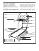
10. If necessary, move the incline trainer to the desired location (see HOW TO MOVE THE INCLINE TRAINER on page 28). 10 After the incline trainer is placed in the location where it will be used, make sure that the incline trainer rests firmly on the floor. If the incline trainer rocks even slightly, turn a Leveling Foot (77) as needed until the rocking motion is eliminated. 77 11. Make sure that all parts are properly tightened before you use the incline trainer.
THE CHEST HEART RATE MONITOR HOW TO PUT ON THE HEART RATE MONITOR • Store the heart rate monitor in a warm, dry place. Do not store the heart rate monitor in a plastic bag or other container that may trap moisture. If the heart rate monitor looks like the one shown in drawing 1, press the transmitter (A) onto the snap fasteners on the chest strap (B). If the heart rate monitor looks like the one shown in drawing 2, insert the tab (C) on one end of the chest strap (D) into one end of the transmitter (E).
HOW TO USE THE INCLINE TRAINER HOW TO CONNECT THE POWER CORD more amps. To avoid overloading the circuit, do not plug other electrical devices, except for lowpower devices such as cell phone chargers, into the surge suppressor or into an outlet on the same circuit. IMPORTANT: If the incline trainer is connected to an AFCI-equipped outlet and your circuit breaker trips repeatedly when the incline trainer is used, see the front cover of this manual to purchase an arc filter.
CONSOLE DIAGRAM FEATURES OF THE CONSOLE In addition, the console features a selection of workouts. Each workout automatically controls the speed and incline of the incline trainer as it guides you through an effective exercise session. The advanced incline trainer console offers a selection of features designed to make your workouts more effective and enjoyable. You can even listen to your favorite workout music or audio books with the console’s sound system while you exercise.
HOW TO TURN ON THE POWER HOW TO USE THE TOUCH SCREEN IMPORTANT: If the incline trainer has been exposed to cold temperatures, allow it to warm to room temperature before you turn on the power. If you do not do this, you may damage the console displays or other electrical components. The console features a tablet with a full-color touch screen. The following information will help you become familiar with the tablet’s advanced technology: Plug in the power cord (see page 16).
HOW TO SET UP THE CONSOLE 6. Calibrate the incline system. Before using the incline trainer for the first time, set up the console. First, touch your name in the upper-left corner. Next, select the settings main menu. Then, select the maintenance section, touch the Calibrate Incline button, and then touch the Begin button to calibrate the incline system. See step 4 on page 25 for more information. 1. Connect to your wireless network.
HOW TO USE THE MANUAL MODE Note: If the walking belt is moving at a high speed and you adjust the incline below 0% or above 15.5%, the speed of the walking belt may automatically decrease. 1. Insert the key into the console. See HOW TO TURN ON THE POWER on page 18. Note: It may take some time for the console to be ready for use. Note: The first time you use the incline trainer, you must calibrate the incline system (see step 4 on page 25). 2. Select the main menu. 5.
• The average speed of the walking belt HOW TO USE A MAP WORKOUT • A track representing 1/4 mile (400 m) Note: To use a map workout, the console must be connected to a wireless network (see HOW TO USE THE WIRELESS NETWORK MODE on page 26). If desired, adjust the volume by pressing the volume buttons on the console. 1. Insert the key into the console. To pause the workout, tap the screen or press the Stop button on the console. To continue the workout, touch the Resume button or the Start button.
5. Monitor your progress with the display modes. If you make a mistake, you can use the Undo button on the left side of the screen. See step 5 on page 20. The screen will display the elevation and distance stats for your workout. If desired, you can change the default speed. 6. Measure your heart rate if desired. See step 6 on page 21. 4. Save your workout. 7. Turn on the fan if desired. Touch the Save New Workout button in the lowerleft corner of the screen.
HOW TO USE A DISTANCE OR TIME WORKOUT 5. Select a distance or time workout that you have previously added to your schedule on iFit.com. Note: To use a distance or time workout, the console must be connected to a wireless network (see HOW TO USE THE WIRELESS NETWORK MODE on page 26). An iFit account is also required. Touch the calendar icon to download a distance or time workout from your schedule. Note: Before workouts will download, you must add them to your schedule on iFit.com. 1.
HOW TO USE THE SLED PUSH FEATURE HOW TO USE THE EQUIPMENT SETTINGS SECTION 1. Insert the key into the console. 1. Select the settings main menu. See HOW TO TURN ON THE POWER on page 18. See step 1 at the left. 2. Select the main menu. 2. Select the equipment settings section. See step 2 on page 20. In the settings main menu, scroll to the Equipment Settings section. Note: Slide or flick the screen to scroll up or down through the options if necessary. 3.
HOW TO USE THE MAINTENANCE SECTION 4. Calibrate the incline system of the incline trainer. 1. Select the settings main menu. Touch the Calibrate Incline button. Then, touch the Begin button to calibrate the incline system. The incline trainer will automatically rise to the maximum incline level, lower to the minimum incline level, and then return to the starting position. This will calibrate the incline system. Touch the Cancel button to return to the maintenance section.
HOW TO USE THE WIRELESS NETWORK MODE An information box will ask if you want to connect to the wireless network. Touch the Connect button to connect to the network or touch the Cancel button to return to the list of networks. If the network has a password, touch the password entry box. A keyboard will appear on the screen. To view the password as you type it, touch the Show Password checkbox. The console features a wireless network mode that allows you to set up a wireless network connection. 1.
HOW TO USE THE SOUND SYSTEM WITH A BLUETOOTH DEVICE HOW TO USE THE SOUND SYSTEM WITH AN AUDIO CABLE 1. Place or hold your Bluetooth-enabled device near the console. To play music or audio books through the console sound system while you exercise, plug a 3.5 mm male to 3.5 mm male audio cable (not included) into the jack on the console and into a jack on your personal audio player; make sure that the audio cable is fully plugged in. Note: To purchase an audio cable, see your local electronics store. 2.
HOW TO MOVE THE INCLINE TRAINER Before moving the incline trainer, insert the key into the console (A), raise the incline to the maximum incline level, remove the key, and unplug the power cord. Carefully roll the incline trainer on the wheels to the desired location, and then lower it to the level position. CAUTION: To reduce the risk of injury, use extreme caution while moving the incline trainer. Do not attempt to move the incline trainer over uneven surfaces.
MAINTENANCE AND TROUBLESHOOTING MAINTENANCE b. After the power cord has been plugged in, make sure that the key is inserted into the console. Regular maintenance is important for optimal performance and to reduce wear. Inspect and properly tighten all parts each time the incline trainer is used. Replace any worn parts immediately. c. Check the power switch located on the incline trainer frame near the power cord. If the switch protrudes as shown, the switch has tripped.
SYMPTOM: The walking belt slows when walked on SYMPTOM: The walking belt is off-center or slips when walked on a. Use only a surge suppressor that meets all of the specifications described on page 16. a. If the walking belt is off-center, first adjust the incline to 40 percent. Next, remove the key and UNPLUG THE POWER CORD.
SYMPTOM: The incline trainer will not connect to the wireless network SYMPTOM: The displays of the console do not function properly a. Make sure that the wireless settings on the console are correct (see page 26). a. If the console does not boot up properly, or if the console freezes and does not respond, reset the console to the factory default settings. IMPORTANT: Doing this will erase all the custom settings you have made to the console. Resetting the console requires two people.
EXERCISE GUIDELINES Burning Fat—To burn fat effectively, you must exercise at a low intensity level for a sustained period of time. During the first few minutes of exercise, your body uses carbohydrate calories for energy. Only after the first few minutes of exercise does your body begin to use stored fat calories for energy. If your goal is to burn fat, adjust the intensity of your exercise until your heart rate is near the lowest number in your training zone.
PART LIST Key No. Qty. 1 2 3 4 5 6 7 8 9 10 11 12 13 14 15 16 17 18 19 20 21 22 23 24 25 26 27 28 29 30 31 32 33 34 35 36 37 38 39 40 41 42 43 44 45 46 47 48 49 50 4 2 16 4 79 4 9 4 8 8 4 2 4 1 1 12 9 4 6 2 2 4 3 1 4 4 4 1 2 1 1 1 1 1 1 1 1 2 1 1 8 1 1 1 4 1 1 1 8 4 Model No. NTL39019.0 R0119B Description Key No. Qty.
Key No. Qty. 101 102 103 104 105 106 107 108 1 8 8 2 6 6 2 4 Description Key No. Qty. Power Supply 5/16" x 3/4" Screw 5/16" Star Washer #8 x 2" Screw #8 x 1 1/4" Screw #8 x 5/8" Machine Screw 3/8" x 1/2" Screw 5/16" x 3/4" Patch Screw 109 110 111 112 113 114 * 1 1 1 1 1 1 – Description Push Bar Bottom Push Bar Top Left Outside Handrail Cover Left Inside Handrail Cover Right Outside Handrail Cover Right Inside Handrail Cover User’s Manual Note: Specifications are subject to change without notice.
5 35 5 43 44 46 11 10 17 40 42 30 39 5 16 11 31 10 38 6 29 5 41 10 5 16 10 5 11 16 16 16 5 5 16 5 10 32 16 33 5 5 6 38 5 36 5 5 35 37 29 10 11 34 5 EXPLODED DRAWING A Model No. NTL39019.
17 64 13 8 10 87 62 51 49 54 25 27 49 50 4 17 53 5 61 17 13 66 48 2 23 63 17 5 59 59 85 101 54 19 65 26 10 53 28 23 17 85 23 8 20 4 2 47 5 60 14 49 25 27 19 26 19 59 58 50 57 19 56 49 51 50 51 49 53 25 27 49 51 49 50 49 8 55 7 15 13 27 53 25 7 7 8 13 EXPLODED DRAWING B Model No. NTL39019.
79 78 68 77 45 12 80 45 81 76 69 73 79 9 12 45 76 37 77 45 81 52 21 78 76 74 73 70 9 26 72 9 73 73 71 26 9 52 72 21 EXPLODED DRAWING C Model No. NTL39019.
EXPLODED DRAWING D Model No. NTL39019.
EXPLODED DRAWING E Model No. NTL39019.
ORDERING REPLACEMENT PARTS To order replacement parts, please see the front cover of this manual.