nordictrack.com Model No. NTSY19916.0 Serial No. Write the serial number in the space above for reference. Serial Number Decal ACTIVATE YOUR WARRANTY To register your product and activate your warranty today, go to my.nordictrack.com. CUSTOMER CARE For service at any time, go to nordictrackservice.com. Or call 1-866-608-1798 Mon.–Fri. 6 a.m.–6 p.m. MT Sat. 8 a.m.–12 p.m. MT Please do not contact the store. CAUTION Read all precautions and instructions in this manual before using this equipment.
TABLE OF CONTENTS WARNING DECAL PLACEMENT . . . . . . . . . . . . . . . . . . . . . . . . . . . . . . . . . . . . . . . . . . . . . . . . . . . . . . . . . . . . . . .2 IMPORTANT PRECAUTIONS. . . . . . . . . . . . . . . . . . . . . . . . . . . . . . . . . . . . . . . . . . . . . . . . . . . . . . . . . . . . . . . . . . 3 BEFORE YOU BEGIN. . . . . . . . . . . . . . . . . . . . . . . . . . . . . . . . . . . . . . . . . . . . . . . . . . . . . . . . . . . . . . . . . . . . . . . .5 ASSEMBLY . . . . . . . . .
IMPORTANT PRECAUTIONS WARNING: To reduce the risk of serious injury, read all important precautions and instructions in this manual and all warnings on your strength system before using your strength system. ICON assumes no responsibility for personal injury or property damage sustained by or through the use of this product. 1. It is the responsibility of the owner to ensure that all users of the strength system are adequately informed of all precautions. the strength system.
STANDARD SERVICE PLANS all 4
BEFORE YOU BEGIN Congratulations for selecting the revolutionary NORDICTRACK® FUSION CST strength system. The FUSION CST strength system is unlike any ordinary strength system. Whether your goal is to tone your body, build dramatic muscle size and strength, or improve your cardiovascular system, the strength system has an array of innovative features that will help you to achieve the specific results you want. after reading this manual, please see the front cover of this manual.
ASSEMBLY • Due to the size and weight of the strength system, assembly requires two or three persons. • In addition to the included tool(s), assembly requires the following tools: one adjustable wrench • Place all parts in a cleared area and remove the packing materials. Do not dispose of the packing materials until you finish all assembly steps. Assembly may be easier if you have your own set of wrenches. To avoid damaging parts, do not use power tools.
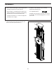
2. Tip: To protect the floor or carpet from damage, place a mat under the strength system. 2 Attach the Right Leg (44) to the right side of the Frame (1) with four M10 x 25mm Hex Screws (101); start all the Hex Screws, and then tighten them. Attach the Left Leg (66) in the same way.
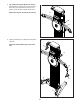
3. Tip: Avoid pinching the Rope (not shown). With the help of another person, pivot the right Tower Arm (19) upward and secure it to the Frame (1) with an M10 x 30mm Screw (100). 3 Repeat this step for the left Tower Arm (19). 19 1 100 19 4. Attach a Handle (37) to a Rope End (35) with a Clip (36). 4 Attach the other Handles (37) in the same way.
5. Identify the Front and Rear Bottom Covers (67, 109) and press them into place as shown. 5 109 67 6. Plug the Power Adapter (126) into the receptacle on the rear of the strength system. 6 126 Note: To plug the Power Adapter (126) into an outlet, see HOW TO PLUG IN THE POWER ADAPTER on page 11. 7. G o to my.nordictrack.com on your computer and register your product.
THE CHEST HEART RATE MONITOR HOW TO PUT ON THE HEART RATE MONITOR • Store the heart rate monitor in a warm, dry place. Do not store the heart rate monitor in a plastic bag or other container that may trap moisture. If the heart rate monitor looks like the one shown in drawing 1, press the transmitter (A) onto the snap fasteners on the chest strap (B). If the heart rate monitor looks like the one shown in drawing 2, insert the tab (C) on one end of the chest strap (D) into one end of the transmitter (E).
HOW TO USE THE STRENGTH SYSTEM This section explains how to adjust the strength system. See the EXERCISE GUIDELINES on page 18 and page 19 for important information about how to get the most benefit from your exercise program. Also, refer to the accompanying exercise guide to see the correct form for each exercise. Make sure that all parts are properly tightened each time the strength system is used. Replace any worn parts immediately.
HOW TO USE THE TABLET HOLDER IMPORTANT: The Tablet Holder (68) is designed for use with most full-size tablets. Do not place any other electronic device or object in the Tablet Holder. Do not set anything on top of the Tablet Holder. 68 A To insert a tablet into the Tablet Holder (68), slide it upward, set the tablet in the tray (A), and then pull the Tablet Holder downward over the top edge of the tablet. Make sure that the tablet is firmly secured in the Tablet Holder.
CONSOLE DIAGRAM FEATURES OF THE CONSOLE The advanced console offers an array of features designed to make your workouts more effective and enjoyable. Interactive iFit App Download the interactive iFit app to access the advanced features of your FUSION CST. The iFit app provides you with an interactive and immersive workout experience, with high-energy, time-saving combination strength and cardio workouts led by virtual personal trainers.
HOW TO USE THE CONSOLE 4. Wear the included chest heart rate monitor and measure your heart rate if desired. 1. Press the power button to turn on the console. You can wear the included chest heart rate monitor to measure your heart rate. To use the chest heart rate monitor, see THE CHEST HEART RATE MONITOR on page 10. Note: The console is compatible with all BLUETOOTH® Smart heart rate monitors. When you turn on the console, the display will turn on. The console will then be ready for use. 2.
HOW TO CONNECT YOUR HEART RATE MONITOR TO THE CONSOLE Note: If there is more than one compatible heart rate monitor near the console, the console will connect to the heart rate monitor with the strongest signal. To use the included chest heart rate monitor, see THE CHEST HEART RATE MONITOR on page 10. To disconnect your heart rate monitor from the console, press and hold the Bluetooth Smart button on the console until the LED on the console turns solid green.
MAINTENANCE AND TROUBLESHOOTING HOW TO MAINTAIN THE STRENGTH SYSTEM See EXPLODED DRAWING B on page 23. Identify the Rear Shroud (59). Remove the four #8 x 3/4" Screws (86) and the Rear Shroud from the strength system. Regular maintenance is important for optimal performance and to reduce wear. Inspect and properly tighten all parts each time the strength system is used. Replace any worn parts immediately. Next, locate the Reed Switch (25). Slightly loosen the indicated screw (A).
HOW TO TIGHTEN THE ROPES The ropes may stretch over time. If there is slack in the ropes before resistance is felt, the ropes should be tightened. To tighten the ropes, first unplug the power adapter, and then follow the steps below. See assembly step 5 on page 9. Remove the Front and Rear Bottom Covers (67, 109) from the bottom of the strength system. See EXPLODED DRAWING B on page 23. Identify the Rear Shroud (59) on the back of the strength system.
CARDIO EXERCISE GUIDELINES Burning Fat—To burn fat effectively, you must exercise at a low intensity level for a sustained period of time. During the first few minutes of exercise, your body uses carbohydrate calories for energy. Only after the first few minutes of exercise does your body begin to use stored fat calories for energy. If your goal is to burn fat, adjust the intensity of your exercise until your heart rate is near the lowest number in your training zone.
STRENGTH EXERCISE GUIDELINES FOUR TYPES OF STRENGTH WORKOUTS to determine the appropriate length of time for each workout, and the numbers of repetitions and sets to complete. Progress at your own pace and be sensitive to your body’s signals. Follow each workout with at least one day of rest. Note: A “repetition” is one complete cycle of an exercise, such as one sit-up. A “set” is a series of repetitions.
PART LIST Key No. Qty. 1 2 3 4 5 6 7 8 9 10 11 12 13 14 15 16 17 18 19 20 21 22 23 24 25 26 27 28 29 30 31 32 33 34 35 36 37 38 39 40 41 42 43 44 45 46 47 48 49 50 1 1 2 2 1 1 1 6 6 1 2 2 2 1 1 1 1 1 2 2 1 1 1 1 1 2 6 6 6 3 3 6 6 6 6 6 6 1 2 2 1 1 1 1 4 2 2 2 4 1 Model No. NTSY19916.0 R0518A Description Key No. Qty.
Key No. Qty. 101 102 103 104 105 106 107 108 109 110 111 112 113 114 115 8 1 1 1 2 19 11 1 1 2 2 5 1 1 3 Description Key No. Qty.
92 92 37 5 115 32 105 6 94 94 33 29 36 35 34 66 7 76 80 37 102 51 9 99 43 45 99 4 8 84 37 48 49 19 118 79 76 27 37 28 117 48 49 50 76 116 74 85 45 1 98 111 87 82 86 8 89 38 4 3 39 96 10 22 18 99 99 93 19 9 77 33 37 32 61 62 63 30 119 124 86 13 14 104 8 9 64 63 60 35 36 34 117 118 107 11 8 56 9 16 101 91 56 106 54 107 56 106 120 106 54 106 55 56 107 106 120 107 106 13 97 97 9 42 8 101 44 106 88
72 15 71 73 53 81 81 83 86 68 70 127 69 23 67 110 75 65 57 86 129 86 75 58 83 83 41 123 126 59 86 122 75 86 75 109 125 EXPLODED DRAWING B Model No. NTSY19916.
ORDERING REPLACEMENT PARTS To order replacement parts, please see the front cover of this manual.