Model No. NETL12814.1 Serial No. Write the serial number in the space above for reference. USER’S MANUAL Serial Number Decal CUSTOMER SERVICE UNITED KINGDOM Call: 08457 089 009 From Ireland: 053 92 36102 Website: www.iconsupport.eu E-mail: csuk@iconeurope.com Write: ICON Health & Fitness, Ltd. c/o HI Group PLC Express Way CASTLEFORD WF10 5QJ UNITED KINGDOM AUSTRALIA Call: 1800 993 770 E-mail: australiacc@iconfitness.
TABLE OF CONTENTS WARNING DECAL PLACEMENT . . . . . . . . . . . . . . . . . . . . . . . . . . . . . . . . . . . . . . . . . . . . . . . . . . . . . . . . . . . . . . .2 IMPORTANT PRECAUTIONS. . . . . . . . . . . . . . . . . . . . . . . . . . . . . . . . . . . . . . . . . . . . . . . . . . . . . . . . . . . . . . . . . . 3 BEFORE YOU BEGIN. . . . . . . . . . . . . . . . . . . . . . . . . . . . . . . . . . . . . . . . . . . . . . . . . . . . . . . . . . . . . . . . . . . . . . . .5 PART IDENTIFICATION CHART.
IMPORTANT PRECAUTIONS WARNING: To reduce the risk of burns, fire, electric shock, or injury to persons, read all important precautions and instructions in this manual and all warnings on your treadmill before using your treadmill. ICON assumes no responsibility for personal injury or property damage sustained by or through the use of this product. 1. It is the responsibility of the owner to ensure that all users of this treadmill are adequately informed of all warnings and precautions. 12.
21. Do not attempt to move the treadmill until it is properly assembled. (See ASSEMBLY on page 7 and HOW TO FOLD AND MOVE THE TREADMILL on page 29.) You must be able to safely lift 45 lbs. (20 kg) to move the treadmill. 26. 22. When folding or moving the treadmill, make sure that the storage latch is holding the frame securely in the storage position. 23. Do not change the incline of the treadmill by placing objects under the treadmill.
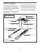
BEFORE YOU BEGIN Thank you for selecting the revolutionary NORDICTRACK® T 13.5 treadmill. The T 13.5 treadmill offers an impressive selection of features designed to make your workouts at home more effective and enjoyable. And when you’re not exercising, the unique treadmill can be folded up, requiring less than half the floor space of other treadmills. reading this manual, please see the front cover of this manual.
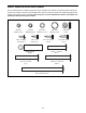
PART IDENTIFICATION CHART Use the drawings below to identify small parts used for assembly. The number in parentheses below each drawing is the key number of the part, from the PART LIST near the end of this manual. The number following the key number is the quantity used for assembly. Note: If a part is not in the hardware kit, check to see whether it is preattached. Extra parts may be included.
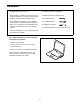
ASSEMBLY • Assembly requires two persons. • To identify small parts, see page 6. • Place all parts in a cleared area and remove the packing materials. Do not dispose of the packing materials until you finish all assembly steps. • Assembly requires the following tools: the included hex key • After shipping, there may be an oily substance on the exterior of the treadmill. This is normal. If there is an oily substance on the treadmill, wipe it off with a soft cloth and a mild, non-abrasive cleaner.
2. Make sure that the power cord is unplugged. 2 Press the two Base Caps (74) into the Base (94) if they are not already in the Base. Wire 81 Tie 81 Remove the tie securing the Upright Wire (81) to the front of the Base (94). Identify the Right Upright (90). Remove and discard the indicated screw (A). Have a second person hold the Right Upright near the Base (94). 90 74 Wire Tie See the inset drawing. Tie the wire tie in the Right Upright (90) securely around the end of the Upright Wire (81).
4. Insert a Wheel Spacer (63) into a Front Wheel (62). Hold the Front Wheel inside the bottom of the Right Upright (90), and insert a 3/8" x 4" Screw (7) with a 3/8" Star Washer (13) into the Right Upright and the Front Wheel. Do not fully tighten the Screw yet. 4 Repeat this step with the Left Upright (not shown). 90 62 13 63 7 5. Place a piece of packing material (B) under the right side of the Base (94). Hold the Right Upright (90) against the Base. Make sure not to pinch the Upright Wire (81).
6. Remove and save the four indicated 5/16" x 3/4" Screws (4). 6 4 Identify the Left and Right Base Covers (82, 83). Slide the Left Base Cover onto the Left Upright (89), and slide the Right Base Cover onto the Right Upright (90). Do not press the Base Covers into place yet. 89 4 82 90 83 7. Orient the Console Base Back (104) as shown and carefully slide it onto the Uprights (89, 90).
8. Attach a Handrail (86) to the Right Upright (90) with two 5/16" x 2 1/2" Screws (28) and two 5/16" Star Washers (11). Be careful not to pinch the Upright Wire (81). Do not fully tighten the Screws yet. 8 28 C 11 86 Attach the other Handrail (86) to the Left Upright (89) in the same way. Note: There are no wires on the left side. 28 Remove and discard the four indicated screws (C). 89 C 86 11 90 81 9. Position the Pulse Crossbar (93) with the pulse wire (D) on the left side as shown.
10. Set the console assembly face down on a soft surface to avoid scratching the console assembly. 10 1 31 Attach the Right and Left Trays (27, 36) with eight #8 x 1/2" Screws (1). Do not overtighten the Screws. 36 1 Then, remove and save the four indicated 1/4" x 1/2" Screws (31). 1 27 1 Console Assembly 11. With the help of a second person, hold the console assembly near the left Handrail (86).
12. With the help of a second person, hold the console assembly near the right Handrail (86). 12 Console Assembly Make sure that the Upright Wire (81) is inserted through the two looped Cable Ties (99). 99 Route the Upright Wire (81) as shown, and insert the Upright Wire into the gap indicated by the arrow. 81 99 86 13. Set the console assembly on the brackets on the Handrails (86). Be careful not to pinch any wires.
. Set the Console (80) on the Console Base (64). Make sure that none of the wires from the Console are pinched. 14 Attach the Console (80) with six #8 x 3/4" Screws (2). 80 Wires 64 2 15. Connect the ground wires (E), the 8-pin wires (F), the 5-pin wires (G), and the four speaker wires (H). Note: The Upright Wire (81) has 8 pins, the pulse wire (D) has 5 pins, and the speaker wires (H) have 2 pins. 2 15 See the inset drawing.
16. See the side view drawing. Slide the Console Base Back (104) upward to the handrail assembly (I). Make sure that the flange on the Console Base Back slides into the handrail assembly. 16 H Note: You will need to tip the Console Base Back (104) so that the flange can fit into the handrail assembly (I). Also, the speaker wires (H) need to fit into the slots in the Console Base Back. Slot Slot Tighten ten #8 x 3/4" Screws (2) into the Console Base Back (104) in the indicated locations.
18. Attach the Console Cover (105) with two #8 x 3/4" Screws (2). 18 Tighten the six 3/8" x 4" Screws (7). Then, press the Base Covers (82, 83) into place. 105 2 82 7 83 7 19. Note: If assembled on a smooth surface, the treadmill may roll forward during this step. 19 Raise the Frame (56) to the upright position. Have a second person hold the Frame until step 21 is completed. Brackets 38 Remove the two 5/16" x 3/4" Screws (4) from the Latch Crossbar (38).
20. Orient the Storage Latch (53) so that the decal is facing away from the treadmill as shown. 20 K Attach the lower end of the Storage Latch (53) to the bracket on the Base (94) with a 5/16" x 1 3/4" Bolt (6) and a 5/16" Nut (12). Raise the Storage Latch (53) to a vertical position. Then, remove and discard the tie (K). 53 Decal 12 21. Align the upper end of the Storage Latch (53) with the bracket on the Latch Crossbar (38). Insert a 5/16" x 2 1/4" Bolt (3) through the bracket.
THE CHEST HEART RATE MONITOR HOW TO PUT ON THE HEART RATE MONITOR The heart rate monitor consists of a chest strap and a sensor. Insert the tab on one end of the chest strap into the hole in one end of the sensor as shown. Then, press the end of the sensor under the buckle on the chest strap. The tab should be flush with the front of the sensor.
SP HOW TO USE THE TREADMILL HOW TO PLUG IN THE POWER CORD Follow the steps below to plug in the power cord. This product must be earthed. If it should malfunction or break down, earthing provides a path of least resistance for electric current to reduce the risk of electric shock. This product’s power cord has an equipment-earthing conductor and an earthing plug. IMPORTANT: If the power cord is damaged, it must be replaced with a manufacturer-recommended power cord. 1.
CONSOLE DIAGRAM FEATURES OF THE CONSOLE The treadmill console offers an impressive array of features designed to make your workouts more effective and enjoyable. When you use the manual mode, you can change the speed and incline of the treadmill with the touch of a button. As you exercise, the console will display instant exercise feedback. You can even measure your heart rate using the handgrip heart rate monitor or the chest heart rate monitor.
HOW TO TURN ON THE POWER HOW TO USE THE MANUAL MODE IMPORTANT: If the treadmill has been exposed to cold temperatures, allow it to warm to room temperature before you turn on the power. If you do not do this, you may damage the console displays or other electrical components. 1. Insert the key into the console. Plug in the power cord (see page 19). Next, locate the power switch on the treadmill frame near the power cord. Press the power switch into the reset position.
5. Follow your progress with the displays. Press the Home button to return to the default menu (see THE SETTINGS MODE on page 27 to set the default menu). If necessary, press the Home button again. As you walk or run on the treadmill, the display can show the following workout information: • The elapsed time When an iFit module is connected, the wireless symbol at the top of the display will show the strength of your wireless signal. Four arcs indicate full signal strength.
7. Turn on the fan if desired. When you select an onboard workout, the display will show the duration of the workout and the name of the workout. In addition, a profile of the speed settings of the workout will appear in the matrix. If you select a calorie workout, the approximate number of calories you will burn will appear in the name of the workout. The fan features several speed settings and an auto mode.
Note: The calorie goal is an estimate of the number of calories that you will burn during the workout. The actual number of calories that you burn will depend on various factors such as your weight. In addition, if you manually change the speed or incline of the treadmill during the workout, the number of calories you burn will be affected.
5. Measure your heart rate if desired. 3. Select a user. See step 6 on page 22. If more than one user is registered, you can switch users in the iFit main screen. Press the increase and decrease buttons next to the Enter button to select a user. 6. Turn on the fan if desired. See step 7 on page 23. 4. Select an iFit workout. 7. When you are finished exercising, remove the key from the console. To select an iFit workout, press one of the iFit buttons.
5. Start the workout. 8. Turn on the fan if desired. See step 3 on page 23. See step 7 on page 23. During some workouts, an audio coach may guide you through your workout. You can select an audio setting for your audio coach (see THE SETTINGS MODE on page 27). 9. When you are finished exercising, remove the key from the console. To stop the workout at any time, press the Stop button. The time will begin to flash in the display.
THE SETTINGS MODE console. However, when you remove the key, the displays will remain lit, although the buttons will not function. If the demo mode is turned on, the word ON will appear in the matrix. To turn on or turn off the demo mode, press the Enter button. The console features a settings mode that keeps track of treadmill information and allows you to personalize console settings. 1. Select the settings mode.
HOW TO ADJUST THE CUSHIONING SYSTEM For more firmness, turn a cushion to the position shown in drawing 1; for less firmness, turn the cushion to the position shown in drawing 2. Adjust the other cushions in the same way. Note: Make sure that the cushions on the left and right sides of the treadmill are set to the same firmness level. The faster you run on the treadmill, or the more you weigh, the firmer the walking platform should be.
HOW TO FOLD AND MOVE THE TREADMILL HOW TO FOLD THE TREADMILL HOW TO MOVE THE TREADMILL To avoid damaging the treadmill, adjust the incline to zero before you fold the treadmill. Then, remove the key and unplug the power cord. CAUTION: You must be able to safely lift 45 lbs. (20 kg) to raise, lower, or move the treadmill. Before moving the treadmill, fold it as described at the left. CAUTION: Make sure that the storage latch is locked in the storage position. Moving the treadmill may require two people.
MAINTENANCE AND TROUBLESHOOTING MAINTENANCE SYMPTOM: The power turns off during use Regularly clean the treadmill and keep the walking belt clean and dry. First, press the power switch into the off position and unplug the power cord. Wipe exterior parts of the treadmill with a damp cloth and a small amount of mild soap. IMPORTANT: Do not spray liquids directly onto the treadmill. To avoid damage to the console, keep liquids away from the console. Then, thoroughly dry the treadmill with a soft towel. a.
Locate the Reed Switch (52) and the Magnet (50) on the left side of the Pulley (49). Turn the Pulley until the Magnet is aligned with the Reed Switch. Make sure that the gap between the Magnet and the Reed Switch is about 1/8 in. (3 mm). If necessary, loosen the #8 x 3/4" Tek Screw (14), move the Reed Switch slightly, and then retighten the Screw. Reattach the Motor Hood (not shown) with the #8 x 3/4" Screws (not shown) and run the treadmill for a few minutes to check for a correct speed reading. b.
SYMPTOM: The walking belt slips when walked on SYMPTOM: The walking belt is not centered between the foot rails a. F irst, remove the key and UNPLUG THE POWER CORD. Using the hex key, turn both idler roller screws clockwise, 1/4 of a turn. When the walking belt is correctly tightened, you should be able to lift each edge of the walking belt 2 to 3 in. (5 to 7 cm) off the walking platform. Be careful to keep the walking belt centered.
EXERCISE GUIDELINES Burning Fat—To burn fat effectively, you must exercise at a low intensity level for a sustained period of time. During the first few minutes of exercise, your body uses carbohydrate calories for energy. Only after the first few minutes of exercise does your body begin to use stored fat calories for energy. If your goal is to burn fat, adjust the intensity of your exercise until your heart rate is near the lowest number in your training zone.
PART LIST Key No. Qty. 1 2 3 4 5 6 7 8 9 10 11 12 13 14 15 16 17 18 19 20 21 22 23 24 25 26 27 28 29 30 31 32 33 34 35 36 37 38 39 40 41 42 43 44 45 46 47 48 49 50 14 60 1 6 4 1 6 6 4 9 10 2 6 1 2 1 2 1 4 2 2 2 4 2 4 6 1 4 1 4 4 4 6 4 6 1 8 1 6 2 1 1 1 1 1 2 1 4 1 1 Model No. NETL12814.1 R0314A Description Key No. Qty.
Key No. Qty. 101 102 103 104 105 106 107 108 1 2 1 1 1 2 2 1 Description Key No. Qty. Receptacle Console Clamp Right Speaker Cover Console Base Back Console Cover #8 x 5/8" Screw Speaker Heart Rate Monitor 109 110 111 112 113 114 * 2 8 6 2 1 1 – Description Incline Motor Spacer #6 x 1/2" Screw #3 x 3/8" Screw Motor Bushing Filter Motor Plate User’s Manual Note: Specifications are subject to change without notice. For information about ordering replacement parts, see the back cover of this manual.
15 8 26 1 36 2 59 30 34 23 39 40 2 61 37 43 8 26 1 2 57 44 39 15 37 35 8 26 11 4 1 2 40 39 35 23 2 45 37 42 47 37 59 30 34 46 56 35 35 60 19 30 26 39 37 8 1 12 37 34 59 11 4 35 49 3 37 53 39 26 8 1 52 23 14 50 51 100 21 10 55 35 26 39 8 1 112 19 38 46 37 59 30 34 100 23 54 20 12 48 6 21 114 10 10 73 113 10 24 10 10 EXPLODED DRAWING A Model No. NETL12814.
EXPLODED DRAWING B Model No. NETL12814.
EXPLODED DRAWING C 28 98 32 11 79 Model No. NETL12814.
EXPLODED DRAWING D Model No. NETL12814.
ORDERING REPLACEMENT PARTS To order replacement parts, please see the front cover of this manual.