www.nordictrack.com Model No. NTL01009.4 Serial No. Write the serial number in the space above for reference. Serial Number Decal QUESTIONS? If you have questions, or if parts are damaged or missing, DO NOT CONTACT THE STORE; please contact Customer Care. IMPORTANT: Please register this product (see the limited warranty on the back cover of this manual) before contacting Customer Care. 1-800-TO-BE-FIT CALL TOLL-FREE: (1-800-862-3348) Mon.–Fri. 6 a.m.–6 p.m. MT Sat. 8 a.m.–4 p.m. MT ON THE WEB: www.
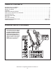
TABLE OF CONTENTS WARNING DECAL PLACEMENT . . . . . . . . . . . . . . . . . . . . . . . . . . . . . . . . . . . . . . . . . . . . . . . . . . . . . . . . . . . . . .2 IMPORTANT PRECAUTIONS . . . . . . . . . . . . . . . . . . . . . . . . . . . . . . . . . . . . . . . . . . . . . . . . . . . . . . . . . . . . . . . .3 BEFORE YOU BEGIN . . . . . . . . . . . . . . . . . . . . . . . . . . . . . . . . . . . . . . . . . . . . . . . . . . . . . . . . . . . . . . . . . . . . . .5 ASSEMBLY . . . . . . . . . . . . .
IMPORTANT PRECAUTIONS WARNING: To reduce the risk of serious injury, read all important precautions and instructions in this manual and all warnings on your treadmill before using your treadmill. ICON assumes no responsibility for personal injury or property damage sustained by or through the use of this product. 1. Before beginning any exercise program, consult your physician. This is especially important for persons over age 35 or persons with pre-existing health problems. carrying 15 or more amps.
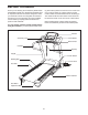
24. Inspect and properly tighten all parts of the treadmill regularly. 20. Never leave the treadmill unattended while it is running. Always remove the key, unplug the power cord, and press the power switch into the off position when the treadmill is not in use. (See the drawing on page 5 for the location of the power switch.) 25. 21. Do not attempt to raise, lower, or move the treadmill until it is properly assembled. (See ASSEMBLY on page 6, and HOW TO FOLD AND MOVE THE TREADMILL on page 24.
BEFORE YOU BEGIN Thank you for selecting the revolutionary NordicTrack® A2750 PRO treadmill. The A2750 PRO treadmill offers an impressive selection of features designed to make your workouts at home more enjoyable and effective. And when youʼre not exercising, the unique treadmill can be folded up, requiring less than half the floor space of other treadmills. ing this manual, please see the front cover of this manual.
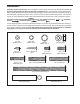
ASSEMBLY Assembly requires two persons. Set the treadmill in a cleared area and remove all packing materials. Do not dispose of the packing materials until assembly is completed. Note: The underside of the treadmill walking belt is coated with high-performance lubricant. During shipping, some lubricant may be transferred to the top of the walking belt or the shipping carton. This is normal and does not affect treadmill performance.
1. Make sure that the power cord is unplugged. 1 With the help of a second person, carefully tip the treadmill onto its left side. Partially fold the Frame (55) so that the treadmill is more stable; do not fully fold the Frame yet. Tie 85 Hole 94 55 Locate the Upright Wire (85), which is bundled at the front of the Base (94). Remove the packaging from the Upright Wire. Insert the Upright Wire into the end of the Base and pull it out of the indicated hole.
3. Identify the Right Upright Spacer (91), which is marked with a “Right” sticker. 3 See the inset drawing. Orient the Right Upright Spacer (91) so that the two rounded corners are positioned as shown. 85 Insert the Upright Wire (85) through the Right Upright Spacer (91). Set the Right Upright Spacer on the Base (94). 91 94 Rounded Corners 91 Rounded Corners 4. Identify the Right Upright (83), which is marked with a “Right” sticker. Orient the Right Upright Cover (86) as shown.
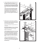
5. Hold a Bolt Spacer (88) inside the lower end of the Right Upright (83). Insert a 3/8" x 5 1/2" Patch Bolt (7) with a 3/8" Star Washer (11) into the Right Upright and the Bolt Spacer. Repeat this step with a second Bolt Spacer (88), 3/8" x 5 1/2" Patch Bolt (7), and 3/8" Star Washer (11). 5 7 83 11 85 91 Hold the Right Upright (83) against the Right Upright Spacer (91). Be careful not to pinch the Upright Wire (85) or the ground wire.
7. Attach the Base Cover (84) to the Base (94) with four #8 x 1/2" Screws (1). Be careful not to overtighten the Screws. 7 84 With the help of a second person, tip the treadmill so that the Base (94) is flat on the floor. 1 94 1 8. Set the console assembly face down on a soft surface to avoid scratching the console. Identify the Right Handrail (79). Hold the Right Handrail near the console assembly. Route the console wire through the large holes in the top and bottom of the Right Handrail.
9. With the help of a second person, hold the sides of the console assembly and place the console assembly near the Right Upright (83) and the Left Upright (not shown). Do not lift the console assembly by the Right Handrail (79) or the Left Handrail (not shown). 9 Connect the Upright Wire (85) to the console wire. See the inset drawing. The connectors should slide together easily and snap into place. If they do not, turn one connector and try again.
11. Start two 1/4" x 1/2" Patch Bolts (8) into the lower ends of both Handrails (78, 79). Tighten all sixteen Patch Bolts (4, 5, 8). Slide the Handrail Covers (77) against the Uprights (82, 83). 11 Console Assembly 4 4 5 83 12. See steps 5 and 6. Tighten the 3/8" x 5 1/2" Patch Bolts (7) used in these steps. Attach the Left Accessory Tray (101) and the Right Accessory Tray (104) to the console assembly with eight #8 x 1/2" Screws (1).
. IMPORTANT: See page 14 and plug in the power cord. Next, see page 16 and turn on the power. 15 IMPORTANT: Make sure to follow all instructions in this step. Then, press the Incline increase button once. When the frame stops moving, remove the key from the console and unplug the power cord. 14. Raise the Frame (55) to the position shown. Have a second person hold the Frame until this step is completed.
OPERATION AND ADJUSTMENT THE PRE-LUBRICATED WALKING BELT Your treadmill features a walking belt coated with highperformance lubricant. IMPORTANT: Never apply silicone spray or other substances to the walking belt or the walking platform. Such substances will cause excessive wear. HOW TO PLUG IN THE POWER CORD DANGER: Improper connection dance with all local codes and ordinances. IMPORTANT: The treadmill is not compatible with GFCI-equipped outlets and may not be compatible with AFCI-equipped outlets.
CONSOLE DIAGRAM FEATURES OF THE CONSOLE The treadmill console offers an impressive array of features designed to make your workouts more effective and enjoyable. When you select the manual mode, you can change the speed and incline with the touch of a button. As you exercise, the console will display continuous exercise feedback. You can even measure your heart rate using the handgrip pulse sensor.
HOW TO TURN ON THE POWER HOW TO USE THE MANUAL MODE IMPORTANT: If the treadmill has been exposed to cold temperatures, allow it to warm to room temperature before turning on the power. If you do not do this, you may damage the console displays or other electrical components. Plug in the power cord (see page 14). Next, locate the power switch on the treadmill frame near the power cord. Make sure that the switch is in the reset position. 1. Insert the key into the console.
4. Change the incline of the treadmill as desired. 6. Measure your heart rate if desired. To change the incline of the treadmill, press the Incline increase or decrease button or one of the 1 Step Incline buttons numbered 0 to 12. Each time you press one of the buttons, the incline will gradually change until it reaches the selected incline setting. Before using the handgrip pulse sensor, remove the sheets of plastic from the metal contacts. In addition, make sure that your hands are clean. 5.
HOW TO USE A PRESET WORKOUT 3. Start the workout. 1. Insert the key into the console. Press the Start button or the Select button to start the workout. A moment after you press the button, the treadmill will automatically adjust to the first speed and incline settings of the workout. Hold the handrails and begin walking. See HOW TO TURN ON THE POWER on page 16. 2. Select a preset workout.
4. Select a display mode and monitor your progress with the display. The workout will continue in this way until the last segment of the profile flashes and the last segment ends. The walking belt will then slow to a stop. Some workouts will be followed by a cool down period. See step 5 on page 17. If you select a time workout, the display will show a stopwatch representing the time remaining in the workout.
HOW TO USE A COMPETITION WORKOUT difficulty for the race by pressing the increase and decrease buttons. Level one is the easiest level and level twelve is the hardest. Press the Continue button. 1. Insert the key into the console. See HOW TO TURN ON THE POWER on page 16. Then, select the distance of the race. You can view more distances by pressing the Next button on the screen. 2. Select a competition workout.
• The number of seconds that you are ahead of the other runners or behind the lead runner. The seconds will appear below the map of the course. If you are behind the other runners, a negative number of seconds will appear. • The bank, or amount, of energy your opponents have left. As the amount of energy in a bank decreases, the speed of that opponent will decrease. • The racing tactics your opponents are using. Your opponents will use different tactics in different situations.
HOW TO USE THE IFIT LIVE MODE The optional iFit Live module allows your treadmill to communicate with your wireless network and unlocks exciting new features. For example, you can download personalized workouts and track and analyze your workout results on the iFit Live website. To purchase an iFit Live module at any time, go to www.iFit.com or call the telephone number on the front cover of this manual. You must have an iFit Live module to use the iFit Live mode.
THE INFORMATION MODE The console features an information mode that keeps track of the total distance that the walking belt has moved and the total number of hours that the treadmill has been used. The information mode also allows you to select miles or kilometers to measure distance, and to turn on and turn off the display demo mode. You can also adjust the contrast level of the display.
HOW TO FOLD AND MOVE THE TREADMILL HOW TO FOLD THE TREADMILL To avoid damaging the treadmill, adjust the incline to the lowest position before you fold the treadmill. Then, remove the key and unplug the power cord. CAUTION: You must be able to safely lift 45 lbs. (20 kg) to raise, lower, or move the treadmill. 1. Hold the metal frame firmly in the location shown by the arrow below. CAUTION: Do not hold the frame by the plastic foot rails. Bend your legs and keep your back straight.
TROUBLESHOOTING Most treadmill problems can be solved by following the simple steps below. Find the symptom that applies, and follow the steps listed. If further assistance is needed, see the front cover of this manual. PROBLEM: The power does not turn on SOLUTION: a. Make sure that the power cord is plugged into a surge suppressor, and that the surge suppressor is plugged into a properly grounded outlet (see page 14).
Remove the four #8 x 3/4" Screws (14) and carefully remove the Motor Hood (61). 61 Locate the Reed Switch (44) and the Magnet (43) on the left side of the Pulley (42). Turn the Pulley until the Magnet is aligned with the Reed Switch. Make sure that the gap between the Magnet and the Reed Switch is about 1/8 in. (3 mm). If necessary, move the Reed Switch slightly using a slotted screwdriver.
PROBLEM: The walking belt is off-center or slips when walked on SOLUTION: a. If the walking belt is off-center, first remove the key and UNPLUG THE POWER CORD. If the walking belt has shifted to the left, use the hex key to turn the left idler roller bolt clockwise 1/2 of a turn; if the walking belt has shifted to the right, turn the left idler roller bolt counterclockwise 1/2 of a turn. Be careful not to overtighten the walking belt.
EXERCISE GUIDELINES WARNING: Before beginning this Burning Fat—To burn fat effectively, you must exercise at a low intensity level for a sustained period of time. During the first few minutes of exercise, your body uses carbohydrate calories for energy. Only after the first few minutes of exercise does your body begin to use stored fat calories for energy. If your goal is to burn fat, adjust the intensity of your exercise until your heart rate is near the lowest number in your training zone.
SUGGESTED STRETCHES The correct form for several basic stretches is shown at the right. Move slowly as you stretch—never bounce. 1. Toe Touch Stretch Stand with your knees bent slightly and slowly bend forward from your hips. Allow your back and shoulders to relax as you reach down toward your toes as far as possible. Hold for 15 counts, then relax. Repeat 3 times. Stretches: Hamstrings, back of knees and back. 1 2. Hamstring Stretch Sit with one leg extended.
PART LIST Model No. NTL01009.4 R0111A To locate the parts listed below, see the EXPLODED DRAWING near the end of this manual. Key No. Qty. 1 2 3 4 5 6 7 8 9 10 11 12 13 14 15 16 17 18 19 20 21 22 23 24 25 26 27 28 29 30 31 32 33 34 35 36 37 38 39 40 41 42 43 44 45 46 47 48 49 50 17 4 1 6 4 1 4 6 8 5 4 2 1 36 2 2 8 12 4 2 4 2 4 1 2 2 2 6 2 4 4 1 2 4 1 1 2 1 2 1 1 1 1 1 1 1 1 1 4 1 Description Key No. Qty.
Key No. Qty. 101 102 103 104 105 106 1 1 1 1 1 1 Description Key No. Qty. Left Accessory Tray Console Base Module Housing Right Accessory Tray Access Door Pulse Bar 107 108 109 110 * 3 1 4 4 – Description Pulse Ground Wire Site Warning Decal #8 x 3/4" Tek Screw Small Platform Cushion Userʼs Manual Note: Specifications are subject to change without notice. For information about ordering replacement parts, see the back cover of this manual. *These parts are not illustrated.
18 32 15 26 25 30 23 59 14 36 35 28 60 15 58 37 25 18 57 26 38 28 30 56 23 110 110 28 109 14 19 109 39 55 18 18 30 40 23 48 28 37 6 42 41 43 110 44 110 109 20 21 28 45 17 51 19 46 50 18 39 30 18 10 17 32 24 54 23 47 53 1 21 33 3 EXPLODED DRAWING A Model No. NTL01009.
EXPLODED DRAWING B Model No. NTL01009.
EXPLODED DRAWING C Model No. NTL01009.
EXPLODED DRAWING D 98 Model No. NTL01009.
ORDERING REPLACEMENT PARTS To order replacement parts, please see the front cover of this manual.