Axiom™ X-1000 Series Dispensing System Operations Manual Models: X-1010 X-1020 P/N 392889, Revision E
NOTICE This is an Asymtek publication which is protected by copyright. Original copyright date 2002. No part of this document may be photocopied, reproduced, or translated to another language without the prior written consent of Asymtek. The information contained in this publication is subject to change without notice. Manuals on the Internet For the convenience of Asymtek customers and field service representatives, copies of this manual can be downloaded from: http://www.asymtek.
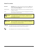
Manual Conventions Bold Text Bold text indicates a software menu or button selection [Click on Go], switch position symbols [ON (I)], Internet address, or label on the dispensing system (Connect to the port labeled Valve 1). [Bracketed Text] [Bracketed Text] indicates a keyboard key to press or a keyboard sequence, such as [Enter] or [Alt+Tab]. Italics Italicized text is used for references to other sections/paragraphs in this manual and for documents outside this manual.
Table of Contents 1 2 INTRODUCTION .................................................................................................. 1-1 1.1 Overview .................................................................................................................. 1-1 1.2 Safety First ............................................................................................................... 1-1 1.3 Manuals Supplied .................................................................................
3.4 Computer Control Panel Features ........................................................................3-14 3.5 Fluidmove Software ..............................................................................................3-15 3.6 Vision System .......................................................................................................3-16 3.6.1 3.6.2 3.6.3 3.7 Vision System Components ....................................................................................
4.3 System Startup .......................................................................................................4-4 4.3.1 4.3.2 4.4 System Shutdown ...................................................................................................4-6 4.4.1 4.4.2 4.4.3 4.5 Positioning the Conveyor and Dispensing Head ....................................................... 4-7 Using the Mouse .......................................................................................................
6 MAINTENANCE ................................................................................................... 6-1 6.1 Overview ................................................................................................................6-1 6.2 Safety First .............................................................................................................6-1 6.2.1 6.2.2 7 Machine Status ....................................................................................................
Table of Figures Figure 2-1 Figure 2-2 Figure 2-3 Figure 2-4 Figure 2-5 Figure 2-6 Typical Warning Label Locations, Front View....................................................2-5 Warning Label Locations, Rear View ................................................................2-6 EMO Locations .................................................................................................2-7 Earthquake Protection, Side View ...................................................................
Figure 4-11 Figure 4-12 Figure 4-13 Figure 4-14 Figure 4-15 Figure 4-16 Figure 4-17 Figure 4-18 Figure 4-19 Fluidmove Production Window ........................................................................4-24 Activating the Needle Heater ..........................................................................4-25 Fluidmove Production Window ........................................................................4-26 Activating the Thermal Control Assembly .............................................
Table of Tables Table 1-1 Table 2-1 Table 2-2 Table 2-3 Table 2-4 Table 2-5 System Configurations: Axiom X-1000 Series ...................................................1-3 Safety Warning Symbols ...................................................................................2-4 Calculation of Overturning Force, X-direction ..................................................2-11 Calculation of Overturning Force, Y-direction ..................................................
1 Introduction 1.1 Overview Congratulations on your choice of the Axiom X-1000 Series Dispensing System! The Axiom X-1000 Series Dispensing System is designed to solve the diverse fluid dispensing needs of the electronics industry. This dispensing system provides a modular approach to hardware, software, and factory integration.
1.4 Training In order to optimize the full capabilities and features of your dispensing system, Asymtek recommends certification for all operators, technicians, and engineers using, programming, and servicing the dispensing system. Asymtek offers several levels of training courses to enable customer operators, technicians, and engineers to become fully certified in dispensing system safety, operation, hardware, software, and fluid applications.
Table 1-1 System Configurations: Axiom X-1000 Series Model Features Applications Recommended Dispensing Valve Series Conveyor Needle Heater X-1010 Surface Mount, Solder Paste, Silver Epoxy Flip Chip Underfill, Dam & Fill, Cavity Fill DJ-9000, DV-7000 DP-3000, DJ-9000, DV-8000 Dual Valve Combinations (option) Dual Valve Combinations (option) • Control by Conveyor Controller • Control by Conveyor Controller • SMEMA Compliant • SMEMA Compliant • O-ring Drive • O-ring Drive • Motorized Ra
2 2.1 Safety Overview This section provides basic safety information necessary for operating and servicing the Axiom X-1000 Series Dispensing System. To further optimize safe dispensing system operation, precautions and recommended practices are included with the procedures throughout this manual. WARNING! 2.2 NOTE CAUTION! Unsafe equipment conditions can result in personal injury or property damage.
2.3 Basic Safety Precautions and Practices Compliance with the following recommended precautions and practices will prevent personal injury or damage to property during X-1000 Series Dispensing System operation and maintenance: 2.3.1 2-2 Safety of Personnel • Only trained personnel should be permitted to perform operation, maintenance, and troubleshooting procedures. • There should always be a second person present when performing maintenance on a system under power.
2.3.2 Preventing Dispensing System and Workpiece Damage • Immediately push the EMO button if dispensing system or a workpiece is in danger of being damaged. • Use standard electrostatic discharge (ESD) precautions when working near sensitive components. Always wear a grounding strap and connect it to the ESD ground before handling workpieces. • Immediately contain and clean up any caustic or conductive fluid spills as recommended in the material manufacturer’s MSDS.
2.4 Safety Warning Labels WARNING! CAUTION! Comply with all safety warning labels or serious injury to personnel or damage to the dispensing system will occur. Worn or damaged labels should be replaced with new labels having the same part number. Warning labels on your Axiom X-1000 Series Dispensing System point out areas where personnel must use extreme caution to prevent serious injury and property damage.
1 2 3 Item Description 1 Hot Surface 2 Hazardous Voltage 3 Heavy Object (side of computer) Figure 2-1 Typical Warning Label Locations, Front View Safety 2-5
1 3 2 4 1 Item Description 1 Hazardous Line Voltage 2 Heavy Object (side of transformer) 3 Fire Hazard 4 Hot Surface Figure 2-2 Warning Label Locations, Rear View 2-6 Safety
2.5 Emergency Shutdown Your Axiom X-1000 Series Dispensing System features EMO buttons that the operator or service technician can use to immediately stop all dispensing operations in case of emergency. This feature helps prevent injury to personnel and damage to the dispensing system and workpieces being processed. Your dispensing system has two EMO buttons. One EMO button is located on the operator’s console, and the second is located on the rear panel of the dispensing system (see Figure 2-3).
2.5.1 Emergency Shutdown Situations As a minimum, activate the EMO in the following situations: WARNING! CAUTION! In an emergency, failure to completely shut down power to the dispensing system with the EMO can cause serious injury to the user and damage to the dispensing system. • If anyone is in immediate danger of being injured by moving parts, hazardous materials, or electrical shock. • If valuable dispensing system components or the workpieces are in danger of being damaged.
2.6 Safety Interlock System The Safety Interlock System is a built-in safety feature that automatically reduces dispensing system servo power when the hatch is opened. This system mainly prevents personnel from being injured by movement of the dispensing head and conveyor. This system consists of the following: • A key attached to the dispensing system hatch that fits into a switch that is attached to the right side doorframe. • A light beacon. • The system computer and Fluidmove software.
2.7 2.7.1 Earthquake Precautions Personnel To prevent injury during an earthquake, all personnel should follow facility earthquake safety guidelines. 2.7.2 System Safe Mode Your X-1000 Dispensing System is designed to automatically go into a safe mode if electrical power is lost due to an earthquake. All hazardous electrical and pneumatic energy is bled out of the system. 2.7.
2.7.4 Seismic Calculations Table 2-2 Calculation of Overturning Force, X-direction Symbol Unit Value Notes Wp lb 961 Total Wt. of Axiom X-1000 h mm 850 Height of CG L1 mm 800 Width of Machine L2 mm 362 Distance from front, RHS of machine to CG in X Symbol Value R (lb) -590.2 Equation Ra=Wp*(.85*L2-.94*h)/L1 Notes For overturning force, 85% of Wp can be used to resist overturning. This analysis is considering Fp HPM = .94Wp.
2.8 Light Beacon The light beacon is a device that displays system status and can warn the operator when fault conditions exist. The beacon has red, yellow, green, and blue lights that can be solid or flashing. The beacon also has an audible alarm. Table 2-2 provides possible reasons for each color indication. Software and hardware share control of the beacon lights. Sometimes, hardware-driven displays override those caused by software conditions and sometimes software-driven displays override.
2.9 Laser Radiation WARNING! The LK Series Height Sensor contains a Class 2 laser. DO NOT look directly at the laser beam. Looking directly at the laser beam may result in serious eye injury. If your X-1000 Series Dispensing System is equipped with the optional laser height sensor (Figure 2-5), the following safety precautions should be observed in addition to the basic system safety precautions: • Operate the laser height sensor in accordance with the operator’s manual included with the equipment.
2.10 Lockout of Electrical and Pneumatic Energy Axiom X-1000 Series Dispensing System electrical and pneumatic components have been designed in accordance with industry-wide safety standards.
5. Disconnect the main power cable. 6. Disconnect the facility pressurized air supply hose from the main air inlet. 7. Place a warning tag on the main air inlet. To restore system to operating condition after servicing is complete: 1. Visually inspect the dispensing system to ensure the following: • All personnel are safely clear of the operating area • A equipment components, covers, and guards are in place • All tools or debris are removed 2. Remove padlock and warning tags. 3.
2.11 Decommissioning Procedures The Axiom System should provide you with years of safe and reliable service. When it becomes necessary to decommission the system, the components should be dispositioned as specified in Table 2-5. Table 2-5 Recommended Decommissioning Procedures Component 2-16 Disposition Consumer Fluid Discard in accordance with local safety/environmental regulations. Aluminum Parts Recycle aluminum conveyor base plate, conveyor rails, panels, doors, and hardware.
3 Component Description 3.1 Overview This section illustrates and describes the features on your Axiom X-1000 Series Dispensing System.
3.2 Front View Features Table 3-1 describes the items illustrated in Figure 3-1.
Table 3-1 Front View Features Item Name Description Light Beacon A device that visually and audibly indicates dispensing system operating status. It has red, yellow, green, and blue status indication lights that can be solid or flashing. Refer to 2.8 Light Beacon for additional information. 2 Work Light A florescent light that illuminates the inside of the dispensing chamber for maintenance or servicing operations whenever the dispensing system is powered up.
3.2.1 Dispensing Chamber Features Table 3-2 describes the items illustrated in Figure 3-2. 1 11 2 10 3 4 9 5 6 7 8 Figure 3-2 Dispensing Chamber Close-up (X-1020 shown) Table 3-2 Dispensing Chamber Features Item Description Dispensing Head Mounted on the X-beam and moved by a positioning system in the X, Y, and Z-axes. Carries the dispensing valve to a precise position over a workpiece in the dispense station.
Table 3-2 Dispensing Chamber Features (continued) Item 5 Name Dispensing Valve (DJ-9000 shown) Description Also referred to as a “pump” or “jet”. Dispenses fluid onto the workpiece. Refer to the applicable dispensing valve manual for detailed information. Part of the dispensing calibration module (DCM). Consists of 6 Needle Sensor Assembly • A slot with fiber-optic sensors to measure dispensing valve needle/nozzle position in the X- and Y-axes.
3.2.2 Conveyor Features Table 3-3 describes the items illustrated in Figure 3-3.
Table 3-3 Conveyor Features Item Name Description 1 Rails The belt pulleys, o-rings, stop pins, board sensors, and clamps are mounted on the rails. Rear rail adjusts to fit the width of the workpiece. 2 Rail Width Motor Moves the rear rail forward and backward to fit the workpiece. 3 Belt Drive Pulleys Transfer belt motor movement to the conveyor belt.
3.2.3 Lower Front Cabinet Features Table 3-4 describes the items illustrated in Figure 3-4.
Table 3-4 Lower Front Cabinet Features Item Name Description 1 View Port Allows the operator to see the valve and fluid air pressure gauges inside the cabinet. 2 Valve 1 Fluid Air Regulator and Gauge Controls/displays air pressure for the Valve 1 fluid syringe. The regulator receives air from the main air regulator located on the back panel of the dispensing system. Refer to 4.5.3 Pneumatic Controls for recommended pressure settings and operating instructions.
3.3 Rear View Features Table 3-5 describes the items illustrated in Figure 3-5.
Table 3-5 Rear View Features Item Name Description 1 Light Beacon A device that visually and audibly indicates system operating status. It has red, yellow, green, and blue status indication lights that can be solid or flashing. Refer to Section 2 – Safety for additional information. 2 Side Air Exhaust Vent (passive) Allows heat from servo shelf components to be exhausted to atmosphere to prevent overheating.
3.3.1 Rear View Features Close-up Table 3-6 describes the items illustrated in Figure 3-6.
Table 3-6 Lower Rear Panel Features Item 1 2 Name Description Main Air Gauge Measures the regulated air pressure supplied to all other dispensing system regulators. Main Circuit Breaker The main power switch for the dispensing system. It protects the dispensing system from facility power surges and controls the flow of facility AC power supplied to the power manager. A flange to the right of the main circuit breaker allows it to be locked in the OFF position during servicing.
3.4 Computer Control Panel Features Table 3-7 describes the items illustrated in Figure 3-7. Refer to Section 7 – Specifications for computer performance specifications.
Table 3-7 Computer Control Panel Item Name Description 1 CD-RW Drive The computer is equipped with a CD-RW Drive. Press the CD Load/Eject Button (item 7 below) to load or eject a writeable compact disk. 2 3.5-inch Disk Drive The computer has a 3.5-inch, 1.4-MB floppy disk drive. Insert disks through the drive door flap. 3 On-Off Switch Press to turn the computer ON and OFF. 4 Power Indicator This LED is green when power to the computer is turned ON.
3.6 Vision System The vision system for your Axiom X-1000 Dispensing System features an ITI Pattern Recognition System with variable red/blue LED lighting. This Vision System is compatible with Asymtek’s Fluidmove dispensing software. The Pattern Recognition System allows the definition of both global and local fiducials and automatically corrects the dispensing process for workpiece misalignment. Global fiducials compensate for lowtolerance fixtures.
Table 3-8 Vision System Features Item Name Description 1 Camera Provides video input to the system computer. It is a miniature, CCDtype (Charge Coupled Device) machine vision, high resolution, black and white camera. 2 Lens System Allows for magnification and focusing of the image being received by the camera. Consists of an aperture, a lens, and a tube. It is quickrelease and vibration-resistant.
3.6.2 Adjusting Light Level and Color CAUTION! Except for lighting adjustments and lens replacement, all other configuration and adjustments should only be performed by a trained service technician. To adjust lighting intensity and color level: 1. Open the hatch, place a workpiece at the conveyor dispense station, and close the hatch. You can also place a workpiece at the upstream conveyor port and click on the Load a in the Fluidmove Programming Window. Board icon 2.
1 2 3 4 Item Description 1 Blue Light Adjustment Slide (in unlinked mode) 2 Red Light Adjustment Slide (in unlinked mode) 3 Color/Brightness Control Mode Button Figure 3-9 Camera Lighting Adjustment Component Description 3-19
3.6.3 Lens Removal and Installation CAUTION! Except for lens replacement and lighting adjustments, all other configuration and adjustments should only be performed by a trained service technician. Remove the lens by turning the lens tube in the direction shown in Figure 3-10. Screw on the replacement lens by turning the lens tube in the opposite direction.
3.7 Height Sensor Asymtek offers a slim-line mechanical height sensor or an optional laser height sensor for Axiom X-1000 Series Dispensing Systems. The height sensor is installed on a bracket attached to the dispensing head next to the dispensing valve needle or nozzle as shown in Figure 3-11. Height sensor is controlled by the system computer using Fluidmove software. Refer to Section 7 – Specifications for height sensor performance specifications.
3.7.1 Mechanical Height Sensor The Mechanical Height Sensor (Figure 3-12) uses a retractable contact probe to locate the surface height of the workpiece. The probe triggers an optical sensor that sends a signal to the Computer where the PMAC motion controller and Fluidmove software automatically record Dispensing Head height. This ensures a uniform distance between the tip of Dispensing Valve needle or nozzle and the workpiece surface. Periodically, the contact probe becomes damaged and must be replaced.
Figure 3-12 Mechanical Height Sensor Figure 3-13 Laser Height Sensor Component Description 3-23
3.7.3 Probe Adjustments When a Height Sensor probe is installed, it may be necessary to adjust the Height Sensor such that its probe is in a position to make accurate measurements. These adjustments include: • Adjusting the probe height in relation to the needle height • Adjusting the distance between the probe tip and the needle tip • Adjusting the upward travel of the probe Making these adjustments can improve throughput and dispensing quality.
1 2 3 Item Description 1 Micrometer 2 Micrometer Locking Screw 3 Slot in Bracket Figure 3-14 Height Sensor Micrometer Setup and Adjustment Component Description 3-25
3.7.3.2 Minor Probe Height Adjustment To make minor adjustments to the probe height: 1. Verify the following: The probe is in the down position The dispensing head is at the top of its Z-axis travel and at the front of the dispensing chamber The dispensing needle has been installed 2. Press OFF (0) on the operator’s console and open the hatch. 3. Using a 0.050-inch hex key, loosen the micrometer locking screw. See Figure 3-14. 4.
1 3 2 1.78 – 2.54 mm (0.07 – 0.10 in.) 1.0 mm (0.04 in.
3.7.3.3 Major Probe Height and Probe-to-Needle Distance Adjustments This procedure can be used to adjust both the height of the Height Sensor probe and the distance the probe is from the dispensing needle. To make major adjustments to the probe height: 1. Verify the following: • The probe is in the down position • The dispensing head is at the top of its Z-axis travel and at the front of the dispensing chamber • The dispensing needle has been installed 2.
1 2 3 Item Description 1 Probe Bushing (with setscrew) 2 Probe 3 Probe Setscrew Access Hole Figure 3-16 Height Sensor Probe Adjustment Component Description 3-29
3.8 Needle Sensor The Needle Sensor is factory-installed at the front of the dispensing chamber as shown in Figure 3-17. The Needle Sensor includes a fiber-optic sensor that measures Dispensing Valve needle/nozzle position in the X- and Y-axes and a tactile sensor that measures the Z-axis position of the needle/nozzle. The Fluidmove software uses this information to automatically compensate for changes in the needle X, Y, or Z-axis.
1 2 5 4 3 Item Description 1 Conveyor Rail (front) 2 Needle Slot 3 LED Indicator 4 Calibration Substrate 5 Tactile Sensor Figure 3-17 Needle Sensor Features Component Description 3-31
3.9 Fluid Heaters There are two basic types of fluid heater that are used with your Axiom X-1000 Dispensing System: • Needle Heater (DV-8000 and DP-3000 Series Dispensing Valves) • Thermal Control Assembly (DJ-9000 Series DispenseJet) These heaters heat dispensing fluids to maintain a consistent viscosity and flowrate, and reduce fluid stringing problems.
3. Loosen the thumbscrew on the side of the heating element. See Figure 3-19. 4. Slide the heating element onto the Luer lock adapter. 5. Tighten the thumbscrew on the side of the heating element. CAUTION! Do not over-tighten the thumbscrew or the Luer lock adapter may be damaged. 6. Connect the power cable to the outlet labeled NEEDLE HEATER on the dispensing head electrical/pneumatic bulkhead. See Figure 3-19. 7. Close the hatch and press ON (l) on the operator’s console.
3.9.2 DJ-9000 Series Nozzle Thermal Control Assembly The thermal control assembly (TCA) (Figure 3-20) is an integral part of the DJ-9000 Series DispenseJet. It maintains a constant fluid temperature by using both a heating element and cooling airflow. To operate the TCA, refer to 4.6.2 Thermal Control Assembly Operation. Refer to Section 7 – Specifications for TCA performance specifications. 3.9.2.
3.10 Weigh Station NOTE Standard on X-1020 Dispensing Systems; option on the X-1010. The weigh station (Figure 3-21) is used to perform periodic mass flow calibrations. The weigh station consists of a small reservoir containing a disposable plastic cup and sheet metal wiper (banjo wiper) that rests on a sensitive electronic balance (scale). The dispensing valve needle tip/nozzle is inserted into the top of the weigh station lid, fluid is dispensed onto the banjo wiper, and the scale weighs the fluid.
3.12 Options Asymtek offers a wide range of options for fine-tuning your dispensing applications.
3.12.2 Heater Tooling NOTE Available only on X-1020 Dispensing Systems. Thermocouple type heaters are standard; RTD type heaters are options. Heater tooling includes contact heaters and impingement heaters. Each heater type is capable of independent temperature regulation with temperature parameters for each station set up within Fluidmove. The software communicates the parameters to the conveyor/heater controller, which regulates heater operation.
3.12.2.1 Contact Heaters A contact heater (Figure 3-24) consists of an interchangeable top plate mounted on a heating unit. Each top plate is equipped with vacuum ports that hold the workpiece against the heater during the heating process. The heater is secured by fasteners on the top of a lift table and connected to power and air supplies using quick-disconnect fittings. Contact heaters use conduction as the heat transfer method.
3.12.2.2 Flexible Impingement Heaters An impingement heater (Figure 3-25) is magnetically attached to the top of a lift table making its position flexible according to the nature of the workpiece. Fixed and or adjustable lift rails maintain the required distance between the workpiece and the heater top plate. The heater is connected to power and air supplies using quick-disconnect fittings. Impingement heaters use convection as the heat transfer method by blowing hot air onto the workpiece from below.
3.12.2.3 Process Development Hot Plate (X-1020) The process development hot plate (P/N PDHP-01, Figure 3-26) converts the system to batch mode for process development with contact heat. It provides precise temperature control required for improving the flow of dispensed fluid. It includes an integral vacuum source with threaded tooling holes for vacuum access or part fixturing. Refer to Section 7 – Specifications for hot plate performance specifications.
3.12.3 SECS/GEM Interface Software The SECS/GEM Interface software (see Figure 3-27) allows the dispensing system’s Fluidmove software to communicate via Ethernet with factory management software running on a host computer connected to the network. Contact Asymtek or an authorized distributor for more information. Figure 3-27 SECS/GEM Tab in FmNT Run Window 3.12.4 CADImport Software NOTE Available on Axiom X-1010 Dispensing Systems only.
3.12.5 Low Fluid Sensors The low fluid sensor automatically detects when material in the syringe or cartridge is low and alerts the operator by activating the light beacon and displaying a message in the Fluidmove Run Window. The operator can continue the dispensing process for a defined number of boards or stop the dispensing process to change the syringe/cartridge. Both magnetic and capacitive sensors are available. Contact Asymtek for specific application suitability. 3.12.5.
3.12.5.2 Magnetic Fluid Level Sensor The magnetic fluid level sensor (Figure 3-29) monitors the fluid level inside a cartridge. A magnet is inserted on top of the follower inside of the fluid cartridge and when the fluid level gets low enough, the sensor detects the magnet on top of the follower and a low fluid warning is issued to the operator. The sensor is held by a bracket that attaches directly to the fluid cartridge.
3.12.6 Under-Board Support System The integrated under-board support system (Figure 3-30) provides support to keep large circuit boards level between conveyor rails. The system consists of an indexed lift table top and magnetically attached support pins. The pins are available as simple mechanical supports or a vacuum type that immobilizes the board as well. Because the pins are magnetically attached to the lift table, they can be easily positioned to avoid interference with under-board components.
3.12.7 Free-Standing Loader (FSL) Asymtek's free-standing upstream and downstream loaders (Figure 3-31) provide flexible integration for factory processes. SMEMA-standard hardware and software protocols provide simplified integration with part handling and processing equipment for in-line system applications. For stand-alone dispensing applications, these loaders are designed to automatically index process carriers and lead frames in and out of magazines.
3.12.8 Wafer Handler System (WHS) The Wafer Handling System (Figure 3-32) is designed to load and unload wafers mounted on frames to Asymtek dispensing systems for flux coating. SMEMA-standard hardware and software protocols provide simplified integration with part handling and processing equipment for in-line system applications.
4 Operation 4.1 Overview Before operating your Axiom X-1000 Dispensing System, it may be helpful to familiarize yourself with the basics of how the system works. This section covers the following topics: 4.
• Up to four solenoid valves which control pneumatics for the dispensing valves • A height sensor that is used to coordinate the Z-axis of the robot with the Z position of the workpiece • A Camera which provides a visual link between the gantry and the workpiece below The visual link is used to coordinate the X and Y-axes of the robot with the X- and Y-axes of the workpiece The second machine is a conveyor which carries the workpiece from an upstream machine, into the X-1000 Dispense Station where flu
4.2.3 Typical Dispensing Process The process illustrated in Figure 4-1 details a simple in-line processing sequence. In an actual production situation, workpieces are in all conveyor stations at the same time with many of the processes occurring simultaneously. Part Loaded Part Arrives at Pre-Dispense Station Stop Pin engages to stop part. Lift Table rises. Heater heats/maintains part temperature.
4.3 System Startup 4.3.1 Startup If necessary, refer to the figures in Section 3 – Component Description to locate system components. To power on the dispensing system: 1. Verify that the dispensing system hatch is closed. 2. Check the EMO Switches on the front and rear of the dispensing system to see if they have been activated. If they have been activated, turn the red EMO knob counterclockwise until it pops out. 3. If not already on, turn the Main Circuit Breaker ON (I).
4. If a message to run a Valve Offsets routine appears, click on OK. A message should appear that indicates the dispensing system is being initialized. 5. When the Fluidmove Message 30416 - Dispenser Motor References Not Found (Figure 4-2) appears, click OK to Home the Dispenser. The Fluidmove Main Window (Figure 4-3) will open. 6. Check to make sure the dispensing head is in the proper Home position. NOTE To start a production run, refer to 4.8 Running Production.
4.4 System Shutdown 4.4.1 Emergency Shutdown WARNING! CAUTION! In an emergency, failure to completely shut down power to the dispensing system with the EMO can cause serious injury to the user and damage to the dispensing system. During an emergency or malfunction, press the red EMO button on the Control Panel or on the back of the dispensing system (see Figure 2-3 for locations).
4.4.3 Service Shutdown We recommend that you incorporate the following steps into your service shutdown routine: 1. Perform a Production Shutdown as described in the previous subsection. 2. Turn OFF (0) the Main Power Circuit Breaker at the rear of the system. Lock out and tag out the power as specified in 2.10 Lockout of Electrical and Pneumatic Energy. 3. Verify pressure at the main air inlet is 0 psi. 4. Disconnect the facility air supply hose.
4.5.1.1 Using the Mouse Using the Mouse to Position the Dispense Head Table 4-1 describes the items illustrated in Figure 4-4. CAUTION! Make sure there are no obstructions before positioning the Dispensing Head or damage to Dispensing Head components or the workpiece may occur. 1 2 6 3 4 5 .
Table 4-1 Dispenser Position Controls Item Name Description 1 Target Box Clicking in the Target Box moves the Dispensing Head to the corresponding position in the dispensing area. 2 XYZ Coordinates Displays the current Dispensing Head position coordinates. Slow Backward (small increments) Fast Backward (large increments) 3 Y-axis Controls (move front/back) Slow Forward (small increments) Fast Forward (large increments) Notes: On DispenseMate® Systems, the tooling plate moves in the Y-axis.
Using the Mouse to Position the Conveyor Table 4-2 describes the items illustrated in Figure 4-5. CAUTION! Make sure there are no obstructions before positioning the conveyor or damage to conveyor components or the workpiece may occur.
Table 4-2 Conveyor Position Controls Item Name Description Rear Rail Slow Backward (small increments) 1 Y-axis Controls (move front/back) Rear Rail Fast Backward (large increments) Rear Rail Slow Forward (small increments) Rear Rail Fast Forward (large increments).
4.5.1.2 Using the Keyboard To operate position controls using Keyboard commands: 1. On the keyboard, press [Ctrl + J] to open the Fluidmove Jog Window. 2. Using the Mouse, click on the Conveyor 1 radio button to activate the conveyor position controls or click on the Dispenser radio button to activate the dispensing head position controls. 3. Press the appropriate keys shown in Table 4-3 to move the selected device (conveyor or dispensing head).
4.5.2 Control Buttons and Switches The location of the primary control buttons and switches that are accessible to the operator are located as shown in Figure 4-6. The function of these buttons and switches is described in Table 4-4.
Table 4-4 Control Buttons and Switches Button/Switch Description Pressing this button causes the power manager to power down potentially hazardous electrical and pneumatic energy sources in the system. The computer and the monitor remain operational. Turn in the direction of the arrows to reset. EMO Button WARNING! Although the system has been powered down, heater tooling and needle heaters still present a thermal hazard until they cool. Controls power to major system components.
4.5.3 Pneumatic Controls The Axiom X-1000 Dispensing System has pneumatic regulators, flowmeters, and associated gauges that control the following: • Main Air (refer to 4.5.3.1 Main Air Regulator) • Fluid Air • Dispensing Valve Air • Cooling Air (DJ-9000) • Tooling Air • Impingement (refer to 4.5.3.2 Pneumatic Controls in the Lower Front Cabinet) Recommended pressure settings are provided in Table 4-5. Refer to 4.5.3.3 for adjustment procedures.
4.5.3.1 Main Air Regulator The main air pressure regulator (Figure 4-7) is a combination filter and regulator with an attached pressure gauge that provides clean, dry, regulated air pressure to the dispensing system from your facility air source. The gauge indicates the regulated air pressure going into the system.
4.5.3.2 Pneumatic Controls in the Lower Front Cabinet Table 4-6 describes the items illustrated in Figure 4-8. Adjustment procedures are described in subsequent paragraphs.
Table 4-6 Pressurized Air Controls Item 1 Name Valve Air Pressure Regulator and Gauge Set Description Controls the air pressure that actuates some dispensing valves (DJ-9000, DP-3000) during dispensing. For details on how air is used for dispensing valve operation, refer to the applicable dispensing valve manual. In dispensing systems with a Dual-Action Dispensing Head, the Valve Air Pressure Regulator and Gauge set can supply both dispensing valves with air pressure.
4.5.3.3 Regulator Adjustment Procedures Main Air Regulator Adjustment 1. Verify that the facility air supply is connected to the Main Air Inlet. 2. At the top of the regulator, locate the regulator adjustment knob. See Figure 4-7. 3. Gently pull up on the adjustment knob to unlock it. Unlock + – Lock 4. While watching the gauge, rotate the adjustment knob: Clockwise to increase pressure up to the desired level. Counterclockwise to decrease pressure.
Fluid and Cooler Air Pressure Regulator Adjustment 1. Verify that the dispensing system is ON. The light beacon will display a green or solid yellow light. 2. Open the lower front cabinet door and find the regulator to be adjusted. See Figure 4-8. + – 3. While watching the appropriate gauge, rotate the adjustment knob: Clockwise to increase pressure. Counterclockwise to decrease pressure.
4.5.4 Connections on the Dispensing Head 4.5.4.1 Pneumatic Connections The pneumatic fittings and hoses supplying pneumatic pressure to components on the dispensing head are color coded for easy identification. Table 4-7 provides fitting and hose colors with a description of their use. See Figure 4-9 for connector locations on the dispensing head bulkheads. Refer to the applicable dispensing valve manual for specific connection details.
1 3 4 2 4-9a Valve 1 Bulkhead 10 5 9 6 4-9b Valve 2 Bulkhead 7 Item Description Item 8 Description 1 Valve 1 Fluid Air Fitting (Silver) 6 Valve 2 ON (Blue) 2 Valve 1 OFF Fitting (Black) 7 Valve 2 OFF (Black) 3 Valve 1 ON Fitting (Blue) 8 Valve 2 Fluid Air Fitting (Silver) 4 Valve 1 Cooler Air (Green) 9 Valve 2 Cooler Air (Green) 5 Toggle Cylinder ON (Blue) 10 Toggle Cylinder OFF (Black) Figure 4-9 Dispensing Head Bulkhead Connectors - Pneumatics 4-22 Operation
4.5.4.2 Electrical Connections The connectors for electrical accessories on the dispensing head are labeled for easy identification as shown in Figure 4-10.
4.6 Operating Fluid Heaters 4.6.1 Needle Heater Operation CAUTION! NOTE The operator can turn the heaters ON and OFF and monitor their function. However, only a trained service technician should set heater parameters. Contact your applications engineer or Asymtek Technical Support for information about setting heater/cooler parameters for your particular application. Operate the needle heater as follows: WARNING! The heater may be hot. Avoid touching heater surfaces or burn injury may occur. 1.
3. In the Heater Control Window (Figure 4-12), locate the loop (channel) for the heater to be operated. 4 3 5 6 1 2 Item Description Item Description 1 Heater Loop - ON 4 Temperature Set Point Column 2 Heater Loop - OFF 5 Present Temperature Value Column 3 Channel (Loop) Name Column 6 Message Column Figure 4-12 Activating the Needle Heater 4. Activate the needle heater by double clicking the icon in the On/Off column until the heater loop icon turns yellow and red.
4.6.2 Thermal Control Assembly Operation CAUTION! NOTE The operator can turn the Thermal Control Assembly on and off and monitor its function. However, only a trained service technician should set heater parameters. Contact your applications engineer or Asymtek Technical Support for information about setting heater/cooler parameters for your particular application. Operate the heater/cooler as follows: WARNING! The heater may be hot. Avoid touching heater surfaces or burn injury may occur. 1.
4. In the Heater Control Window (Figure 4-14), locate the loops (channels) for the heater and cooler to be activated. 4 3 5 6 1 2 Item Description Item Description 1 Heater-Cooler Loop Set - ON 4 Temperature Set Point Column 2 Loop - OFF 5 Present Temperature Value Column 3 Channel (Loop) Name Column 6 Message Column Figure 4-14 Activating the Thermal Control Assembly 5.
4.7 Operating Heater Tooling CAUTION! NOTE The operator can turn the heaters ON and OFF and monitor their function. However, only authorized personnel should set heater parameters. Contact your applications engineer or Asymtek Technical Support for information about setting heater parameters for your particular application. Operate heater tooling as follows: WARNING! The heater may be hot. Avoid touching heater surfaces or burn injury may occur. 1.
3. In the Heater Control Window (Figure 4-16), locate the loop (channel) for the heater to be operated. 4 3 5 6 1 2 Item Description Item Description 1 Heater Loop - OFF 4 Temperature Set Point Column 2 Heater Loop - ON 5 Present Temperature Value Column 3 Channel (Loop) Name Column 6 Message Column Figure 4-16 Activating the Needle Heater 4. Activate the heater by double clicking the icon in the On/Off column until the heater loop icon turns yellow and red.
4.8 Running Production The following procedure assumes that the computer and monitor are on and Fluidmove has been started as described in 4.3.2 Starting Fluidmove Dispensing Software. To start a production run: 1. Verify that the Main Air, Valve, and Fluid pressures are set to the desired level. If not, adjust pressure as described under 4.5.3 Pneumatic Controls. 2. .Verify that all dispensing head accessories are properly connected. See 4.5.4 Connections on the Dispensing Head. 3.
7. In the Production Window, click on the Load button. The Open dialog box will appear. 8. In the Open dialog box, select the program you wish to run and click on Open. See Figure 4-18. The name of the selected program should appear in the Production Window.
9. In the Production Window, click on Run and then click on the Run Production button. This brings up the Run Window. 10. Click on Go ( ) to activate the dispensing process. See Figure 4-19. CAUTION! If the message “Clear conveyor before continuing” appears on the Monitor screen, remove any workpieces from the conveyor before clicking on OK.
4.9 Consumables Consumables are operational support materials for the dispensing process that are discarded after use. WARNING! Consumable materials must be discarded in accordance with local regulations, material manufacturer MSDS recommendations, and facility practice. The items listed in Table 4-8 are consumable materials for the Axiom X-1000 Series Dispensing System that can be ordered from Asymtek or an authorized distributor.
5 Troubleshooting 5.1 Overview If you have difficulty operating your dispensing system, use this section to identify a possible solution to the problem. If you have difficulties not listed in this section, or the suggested solution does not correct the problem, contact Asymtek Technical Support. This section provides troubleshooting information for the following: 5.
5.3 Light Beacon Indications The light beacon may be your first clue to solving a problem with your dispensing system. Table 5-1 explains the meaning of the colored lights on a typical dispensing system and suggested recovery procedures. Table 5-1 Light Beacon Indications Symptom 1. Light Beacon displays a RED light. Possible Cause A. Solid – System in an Emergency Stop condition. All motion, outputs, dispensing valve, and motion controls are disabled. Recovery Procedures 1.
5.4 Software Troubleshooting Use Table 5-2 to identify possible solutions to some Fluidmove software issues. Table 5-2 Software Troubleshooting Symptom Possible Cause Recovery A. Dispensing head has lost its Home reference. Click on OK to Home the Dispensing Head. B. Power may be OFF. Press ON (l) on the operator’s console. 2. Receive “General Protection Fault” message during production run or during programming. Fluidmove has received a bad command. 1. Exit Fluidmove. 3.
5.5 Hardware Troubleshooting Use Table 6-3 through Table 6-10 to determine the possible cause of minor hardware problems, and follow the recommended recovery procedures to resolve the problem. For problems not addressed in this subsection, refer to the Troubleshooting section of the Axiom X-1000 Installation and Service Manual or contact Asymtek Technical Support.
5.5.2 Vision System Table 5-4 describes some minor problems related to Vision System operation, offers possible causes, and suggests some recovery procedures. Refer to 3.6 Vision System for additional information. Table 5-4 Vision System Troubleshooting Symptom Possible Cause Recovery 1. No Image (Fluidmove display window is a solid pink color). Camera is not connected. Verify Camera cable is securely connected to the connector on the top of the Camera. 2.
5.5.3 Height Sensor Table 5-5 describes some minor problems related to height sensor operation, offers possible causes, and suggests some recovery procedures. Refer to 3.7 Height Sensor for additional information. Table 5-5 Height Sensor Troubleshooting Symptom 1. Probe does not drop or retract. Possible Cause Recovery A. Height Sensor cable is not connected. Check cable connection to the Dispense Head Controller electrical interface panel. B. Solenoid is faulty. 1. Check solenoid function: a.
5.5.4 Needle Sensor Table 5-6 describes some minor problems related to Needle Sensor operation, offers possible causes, and suggests some recovery procedures. Refer to 3.8 Needle Sensor for additional information. Table 5-6 Needle Sensor Troubleshooting Symptom 1. Possible Cause Recovery During Setup routine, error indicates that the tactile sensor is already engaged. Tactile sensor cap is stuck in the down position. See Figure 5-1. 2. During Prompted Setup routine, LED does not come ON.
5.5.4.1 Tactile Sensor Error If you receive a Tactile Sensor error while performing any of the previously described setup routines, use the following procedure to remedy the error. NOTE If you continue to receive Tactile Sensor errors after performing the following procedure, contact Asymtek Technical Support. 1. Gently lift the cap off of the Tactile Sensor as shown in Figure 5-1. 2.
5.5.5 Fluid Heaters Table 5-7 describes some minor problems related to fluid heater operation, offers possible causes, and suggests some recovery procedures. Refer to 3.9 Fluid Heaters for additional information. Table 5-7 Needle Heater Troubleshooting Symptom 1. External Type Heater does not heat. Possible Cause Recovery A. There is a loose electrical connection. Make sure all connections are secure. B. Heater is not active. Activate the appropriate heater loop in Fluidmove as specified in 4.6.
5.5.6 Conveyor Table 5-8 describes some minor problems related to conveyor operation, offers possible causes, and suggests some recovery procedures. Refer to 3.2.2 Conveyor Features for additional information. Table 5-8 Conveyor Troubleshooting Symptom 1. Rails or belt will not move. Possible Cause A. EMO button has been activated. Recovery 1. Turn the EMO button counterclockwise until it pops back into position. 2. Press ON (l) on the operator’s console. 2.
Table 5-8 Conveyor Troubleshooting (continued) Symptom 4. Board sensors not sensing when board is present. 5. Board will not index to correct position. 6. Conveyor does not move at all (with Fluidmove position controls). 7. Conveyor jams or does not move. Possible Cause Recovery A. Sensor is not active. Call a trained service technician. B. Sensor is dirty. Clean sensors with a soft cloth or with blown air. C. Sensor is out of adjustment. Call a trained service technician. A.
5.5.7 Heater Tooling Table 5-9 describes some minor problems related to Heater Tooling operation, offers possible causes, and suggests some recovery procedures. Refer to 3.12.2 Heater Tooling for additional information. Table 5-9 Heater Tooling Troubleshooting Symptom 1. Heaters do not turn on. Possible Cause A. EMO button has been activated. Recovery 1. Turn the EMO button counterclockwise until it pops back into position. 2. Press ON (l) on the operator’s console. 5-12 B. Heater loops are not active.
5.5.8 Dispensing Head Table 5-10 describes some minor problems related to dispensing head operation, offers possible causes, and suggests some recovery procedures. For dual-action dispensing heads, refer to 3.12.1 Dual-Action Dispensing Head for additional information. Table 5-10 Dispensing Head Troubleshooting Symptom 1. Dispenses in the wrong X-axis and/or Y-axis position. 2. Dispenses at the wrong Z-axis position. Troubleshooting Possible Cause A. Nozzle/needle is damaged. Recovery 1.
6 Maintenance 6.1 Overview This section describes the recommended periodic maintenance procedures that a trained operator can perform to increase system life and ensure high quality dispensing performance. This section covers the following: 6.
6.3 Record Keeping Record keeping is essential to efficient maintenance. The date and the type of maintenance performed should be recorded in maintenance records for each dispensing system. Keep records of dispensing system wear characteristics unique to your production methods. These records can then be used for planning purposes. TIP 6.4 Scheduled Maintenance WARNING! CAUTION! Only qualified personnel should perform maintenance tasks.
Table 6-1 Recommended Maintenance Maintenance Task Clean purge station boot. Recommended Frequency Daily Instructions 1. Remove the purge station cover. Do not attempt to remove the boot from the cover or the boot may be damaged. 2. Carefully clean the boot and purge station cover with a soft cloth and the cleaning agent recommended by the fluid manufacturer (see the MSDS). 3. Replace purge station cover. Replace purge station cup.
6.5 Replacing Purge Boots Purge boots should be replaced at the intervals recommended in Table 6-1: Tools and Materials Needed • Needle-nosed Pliers • Personal Protective Equipment (as required) • Isopropyl Alcohol • Replacement Purge Boot (see Table 6-2) • Clean Shop Cloth Table 6-2 Purge Boot Colors, Sizes, and Compatible Needles Purge Boot Color Inside Diameter Compatible Needle Gages Asymtek P/N Orange 0.5 mm (0.020 in.) 26, 27, 30, 32 01-0019-00 Pink 0.8 mm (0.031 in.
1 2 Item Description 1 Purge Boot (Table 6-2) 2 Purge Station Cover (P/N 194701) Figure 6-1 Replacing the Purge Boot Maintenance 6-5
6.6 Replacing Purge and Weigh Station Cups The cups in the purge and weigh stations should be replaced at the intervals recommended in Table 6-1. Tools and Materials Needed • Isopropyl Alcohol • 1 oz.
4 1 5 2 3 Item Description 1 Weigh Station Cover (P/N 194543) 2 Banjo Wiper (P/N 02-1570-03) 3 Weigh Station Cup (P/N 58-0030) 4 Purge Station Cover (P/N 194701) 5 Purge Station Cup (P/N 58-0030) Figure 6-2 Replacing Purge and Weigh Station Cups Maintenance 6-7
6.7 Draining the Water Trap The facility air supply may contain moisture that can damage the dispensing system. The water trap condenses this moisture before it enters the dispenser pneumatic system. The operator or technician should drain the water trap weekly or whenever it is full. WARNING! Do not remove the bowl guard protecting the water trap.
1 2 4 3 ` OPEN Item CLOSE Description 1 Regulator 2 Main Air Inlet 3 Drain Knob 4 Water Trap Bowl Guard (bowl inside) Figure 6-3 Draining the Water Trap Maintenance 6-9
6.8 Replacing a Height Sensor Probe If your system is equipped with a mechanical height sensor, you will need to replace the height sensor probe whenever it becomes damaged. NOTE The height sensor probe size is dependent upon which dispensing valve is installed. If you change from one dispensing valve to another, you may also need to change the height sensor probe. Tools and Materials Needed • 0.
6. While holding the probe in place, tighten the setscrew just until the probe is held firmly in place. Remove the hex key and rotate the probe to its former position. 7. Perform adjustments of the probe as specified in 3.7.3 Probe Adjustments to precisely align the probe bend with the needle tip and adjust the probe-to-needle distance. 8. After the probe position has been adjusted, close the hatch and press the ON (l) button on the operator’s console. 9. Perform a Valve Offsets routine in Fluidmove.
1 2 1.78 – 2.54 mm (0.07 – 0.10 in.) 3 1.0 mm (0.04 in.
6.9 Cleaning the Fan Filters The two fans located on the rear and side of the dispensing system help to regulate the internal temperature of the system. The fan on the rear of the dispensing system is an exhaust fan that vents the dispensing chamber. The fan on the side of the servo shelf blows cool air onto the components inside. The covers and filtering sheets should be cleaned or replaced as needed. To clean the fans and vents: 1. Press the OFF (0) button on the operator’s console. 2.
7 Specifications 7.1 Overview This section contains specifications for Axiom X-1010 and Axiom X-1020 Dispensing Systems. These specifications are intended as a convenient reference for personnel planning system relocation, installation, or operation, and other persons that may have an interest in system performance characteristics. This section provides specifications for the following: 7.
7.3 Specifications Table 7-1 Facility Requirements Characteristic Specification System Footprint 1443 mm X 1100 mm (56.8 in. x 43.3 in.) See Figure 7-1 and Figure 7-2. Power (Main) 180–260 VAC single phase, 30 A, 50/60 Hz, connected through a 3 meter cord with NEMA L6-30 male locking plug /female IEC 60309 connector Main Breaker Current Interrupting Capacity 30 amperes Main Breaker AIC Rating 10 kA Air Supply Pressure: 621 kPa (6.1 atm, 90 psi) Flowrate: 28–198.2 liters/min.
Side View Front View Top View Figure 7-1 Dispensing System Dimensions (Typical) Specifications 7-3
Figure 7-2 Dispensing System Service Area Dimensions 7-4 Specifications
Figure 7-3 Center of Gravity Specifications 7-5
Figure 7-4 Weight Distribution 7-6 Specifications
Table 7-3 Dispensing Valve-Related Specifications Characteristic Specification Recommended Dispensing Valves(2) Single Dispense Valve (X-Y)(3) Dual Dispense Valves (X-Y)(3) (Valve 1 / Valve 2) Notes: 1. • DJ-9000 DispenseJet® • DP-3000 Linear Positive Displacement Pump • DV-8000 Heli-Flo® Pump • DV & DJ: (4) 457.2 x 457.2 mm (18.0 x 18.0 in.) • DP: • DV or DJ/DV or DJ: (4) 357.1 x 431.4 mm (14.0 x 17.0 in.) • DV or DJ /DP: (4) 353 x 394 mm (13.9 x 15.5 in.) • DP/DP: 442 x 418 mm (17.
Table 7-5 Positioner System Specifications Characteristic Specification X-Y Motion Type Brushless DC servomotor, low inertia, closed-loop, high-resolution cable drive with multi-encoder feedback Z Motion Type Brushless DC servomotor, rack and pinion with precision encoder feedback X-Y Acceleration 1.0 g peak with S-curve jerk control X-Y Velocity (maximum) 1.0 m/sec (40 in./sec) X-Y Travel 500.4 x 541.0 mm (19.7 x 21.3 in.) Z Travel 89 mm (3.5 in.
Table 7-6 Computer and User Interface Specifications Characteristic Computer Specification ≥500 MHz Celeron PC typically configured as follows: • • • • • • • • • ≥ 64 MB RAM ≥ 20 GB hard drive ≥ 32X speed CD-RW drive Two RS232 ports Dual port RAM card (ISA) Servo controller card (8 axes) Video card 96 bit I/O card Controller Area Network (CAN) interface Operating System Windows NT (FmNT)or Windows XP (FmXP) Dispensing Software Fluidmove for Windows NT, version 4.
Table 7-7 Vision System Specifications Characteristic Camera Specification Type: Miniature, black and white, high-resolution video, CCD Dimensions: 31mm (1.2 in.) wide, 29 mm (1.1 in.) high, 65 mm (2.5 in.) depth Picture Resolution: 768 x 494 pixels Pixel Resolution (X-Y):(2) 0.0099 x 0.0099 mm/pel(3) (0.00039 x 0.0039 in./pel) Field of View: 7.0 x 5.0 mm (0.28 x 0.20 in.) Adjustable Camera Height: 38 mm (1.5 in.) Effective Focal Length: 200 mm (7.
Table 7-8 Height Sensor Specifications Characteristic Specification Mechanical: Repeatability 25 microns @ 25 mm/s (0.001” at 1 in./s), 3 sigma ± 0.025 mm (0.001 in.) Probe Activation Force 5 grams (0.17 oz.) approximate Probe Tip Diameter 0.51 mm (0.02 in.) Probe Retract 10 mm (0.2 in.) (adjustable) Z-axis Acceleration 762 cm/sec2 (300 in/sec2) LK Series Laser: Classification Class 2 Laser, maximum output 0.95 mW Repeatability 25 microns @ 25 mm/s (0.001 in. at 1 in./s), 3 sigma ± 0.
Table 7-10 Fluid Heater Specifications Characteristic Specification Needle Heater (DP, DV): Control Fluidmove software programmable, closed-loop PID controller Temperature Range Ambient to 120 °C (248 °F) Accuracy ±5 °C (33.8 °F) Temperature Sensor Resistance Temperature Detector (RTD) Heating Element Power Output 24 VDC, 1 A, 6 W peak Fuse Rating 3 Amperes Thermal Control Assembly (DJ-9000): Body 6061-T6 Aluminum, Nickel Plated Heating Element Power Output 24 VDC, 14.
Table 7-12 Conveyor Specifications Characteristic Specification Speed Variable, 254 mm/sec (10 in/sec) maximum Carrier Types Auer boats, lead frames, PCBs, or custom carriers Rails Standard: Fixed front with rear rail adjustable in the Y-direction Length: 1100 mm (43.3 in.) Width: 23–460 mm (0.9–18.1 in.) Height: Adjustable from 891–965 mm (35–38 in.) (floor to top of conveyor o-ring) Conforms to SMEMA standard. Control Fluidmove and Conveyor/Heater Controller Edge: 4.
Glossary AC: Alternating Current. Amperes Interrupting Capacity (AIC): Also known as “breaking capacity” or “short circuit rating”. It is the maximum current that an Overcurrent Protection Device can safely interrupt at rated voltage. Area-Fill: Dispensing lines of fluid within a geometric pattern to completely cover an area. ASPA System: Advanced Semiconductor Package Assembly fluid dispensing system. Auer Boat: A carrier used to transport multiple workpieces through the dispensing system.
Dispensing Valve: A device used to control or regulate the flow of material from a pressurized reservoir, such as a syringe. These devices include Valves, Pumps, and Jets. See also Valve, Pump, and Jet. Grounding Strap: A strap worn on the wrist of an Operator and plugged into Operator’s Console jacks to prevent an electrostatic discharge (ESD) that may cause damage to the workpiece. DOAL: Diffuse On-Axis Light.
Needle Sensor: A sensor located on the Axiom X-1020 dispensing calibration module that uses light beams to determine the XY location of the dispensing needle tip. Production Shutdown: When all dispensing has been stopped under non-emergency conditions such as the end of a shift. Needle Sensor Substrate: A ceramic pad near the needle sensor that is dispensed upon during needle location definition routines. Psi: Pounds per Square Inch (lbs/in2). English unit of pressure measurement.
SMEMA: Surface Mount Equipment Manufacturers Association. Established protocol for signal communication between two or more different systems. SMA: Surface Mount Adhesive. An adhesive used for attaching chips to PWBs. SVGA: Super Video Graphics Array. A video card that produces high-quality color images at high resolution. Syringe: A reservoir containing the dispensing fluid that is usually attached to the dispensing valve.
Index B Board Sensor................................................................... 3-7 C CADImport ................................................................... 3-41 Camera features..................................................................... 3-17 lens installation/removal .......................................... 3-20 lighting adjustment................................................... 3-18 location/description ....................................................
H M Heaters, fluid DJ-9000 thermal control assembly ........................... 3-34 needle heater ............................................................ 3-32 operation .................................................................. 4-24 Main Air Inlet................................................................ 3-11 Heaters, substrate contact ...................................................................... 3-38 controller ...........................................................
P Parts - Ordering Consumables ...................................... 4-33 Pattern Recognition System specifications ........................................................... 7-11 Pneumatics ........................................................... 4-14–4-22 Process Development Hot Plate .................................... 3-40 Purge Boot replacement ................................................................ 6-4 sizes ...........................................................................
V Vision System ...................................................... 3-16–3-20 specifications ........................................................... 7-11 troubleshooting .......................................................... 5-5 W Warning Labels ........................................................ 2-4–2-5 Water Trap draining ...................................................................... 6-8 location .....................................................................