
Owner manual

3-4 Component Description
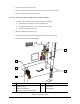
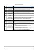
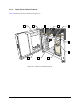
3.2.1 Dispensing Chamber Features
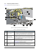
Table 3-2 describes the items illustrated in Figure 3-2.
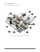
Figure 3-2 Dispensing Chamber Close-up (X-1020 shown)
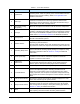
Table 3-2 Dispensing Chamber Features
Item Name Description
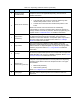
1 Dispensing Head
Mounted on the X-beam and moved by a positioning system in the X,
Y, and Z-axes. Carries the dispensing valve to a precise position
over a workpiece in the dispense station. The Vision System and
height sensor (option) are also mounted on the dispensing head.
2
Electric/Pneumatic
Bulkhead (for Valve 1)
Consists of a sheet metal plate that supports electrical and
pneumatic connectors for accessories on the dispensing head. The
bulkhead for Dispensing Valve 1 is on the left side of the dispensing
head. The bulkhead for Dispensing Valve 2 is mounted on the right
side of the dispensing head.
3
Camera and Lens
The compact, high resolution, black and white camera and its
adjustable, vibration-resistant lens are part of the Vision System.
Used to view work surfaces in the dispensing chamber. Refer to 3.6
Vision System for additional information.
4
Red/Blue Diffuse On Axis
Light
(DOAL)
Provides variable red and blue LED lighting for the camera. Adjusting
the light color and intensity improves video display contrast that
results in accurate fiducial identification on the workpiece.
2
4
8
7
5
1
11
10
6
9
3