Axiom™ Series X-1022 Dual Conveyor Dispensing System Addendum to Axiom X-1000 Series Operations Manual P/N 392889, Revision D Note: In the event of conflict between the manual specified above and this addendum, this addendum shall have precedence.
NOTICE This is an Asymtek publication, which is protected by copyright. Original copyright date 2006. No part of this document may be photocopied, reproduced, or translated to another language without the prior written consent of Asymtek. The information contained in this publication is subject to change without notice. Manuals on the Internet For the convenience of Asymtek customers and field service representatives, copies of this manual can be downloaded from: http://www.asymtek.com/support/manuals.
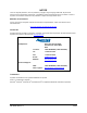
1 Introduction Overview This addendum addresses additional information necessary for configuring, operating, and programming the Axiom X-1022 Dual Conveyor Dispensing System and covers the following topics: • System Features • Positioning the Conveyor • Dual Conveyor Setup • Fluidmove Programming for Dual Lane Systems • Theory of Operation Refer to the Axiom X-1000 Series Operations Manual, the Axiom X-1000 Series Installation and Service Manual, and the Fluidmove User Guide for additional infor
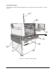
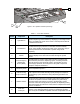
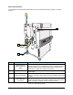
Front View Features This subsection contains functional descriptions of X-1022 components shown in Figure 1-1 through Figure 1-4.
4 5 7 6 Figure 1-1B Operator Controls (Close-up) Table 1-1 Front View Features Item No. Component Description Light Beacon The Light Beacon is a warning device for the operator. The beacon signals a dispensing status condition by displaying a colored light and/or issuing an audible tone. Refer to the Axiom X-1000 Operations Manual for additional information. 2 Hood/Window The Hood/Window allows access to the dispensing area.
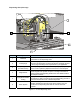
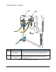
Dispensing Area (Close-up) 1 2 6 3 4 5 Item No. Component 1 Bulkhead 2 Fluid Syringe The Fluid Syringe is mounted on the dispensing valve and contains the fluid to be dispensed. The fluid manufacturer packages the fluid in the syringe according to the requirements of your application. 3 Dispensing Valve (DJ-9000 shown) The Dispensing Valve also referred to as a pump or jet (depending on the mode of operation) dispenses the fluid onto the workpiece.
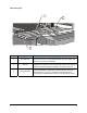
Dual Conveyors 1 2 3 Item No. Component 1 Board Sensor 2 Stop Pin 3 Conveyor Rails Description Fiber-array Board Sensors mounted on top of the conveyor rail detect the presence of the workpiece at each conveyor station and report it to the Conveyor Controller. The Stop Pins are pneumatic devices that physically stop the workpiece at a specific conveyor station. The Conveyor Controller, in conjunction with the Fluidmove software, controls the stop pins. The Conveyor 1 front rail is fixed.
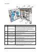
Front Cabinet 2 3 1 4 6 5 Item No. Component Description 1 Precision Fluid Air Regulator and Gauge The Valve 1 Fluid Air Regulator and Gauge set consists of a precision regulator and a digital gauge and controls air pressure for the Dispensing Valve 1 fluid syringe on the Dispensing Head. There is also a Valve 2 Fluid Air Regulator and Gauge set used for systems configured with the Dual-Action Dispensing Head.
Rear View Features This subsection contains functional descriptions of X-1022 components shown in Figure 1-5 through Figure 1-7. 1 3 2 Item No. Component Description 1 Rear Emergency Machine Off Button (EMO) The EMO button is a built-in safety feature located on both the front panel and back panel of the dispensing system. Activating the EMO vents all pressure in the pneumatic system and cuts power to all components, including the computer and monitor.
Pneumatic Regulators and Gauges 1 2 Item No. Component Description 1 Main Air Regulator and Gauge The Main Air Regulator and Gauge controls the air pressure supplied to all other system regulators. The regulator contains an air filter and water trap to ensure that only clean, dry air enters the system. 2 Impingement Heater Air Regulator and Gauge The Impingement Heater Air Regulator and Gauge set supplies air to the impingement flowmeters which regulate the air flow to the impingement heaters.
Rear Connections 1 2 3 4 Item No. Component Description 1 Unloader Upstream Used for programming purposes on upstream unloaders. 2 Loader Downstream Used for programming purposes on downstream loaders. 3 Conveyor 1 SMEMA Connections 4 Conveyor 2 SMEMA Connections The upstream/downstream SMEMA connectors allow for SMEMA communication between the dispensing system and upstream and downstream machines, such as loaders and unloaders.
2 Installation Refer to the Installation section of the Axiom X-1000 Series Installation and Service Manual for standard installation and setup procedures. In most cases, system configuration is performed at the Asymtek factory. Typical Dual Conveyor settings are shown below. Dual Conveyor Setup To configure the Conveyor: 1. Power on the dispensing system and start Fluidmove as described in the Axiom X-1000 Series Operations Manual. 2. In the Fluidmove Main Window, select Configuration>Setup Conveyors.
Figure 2-2 Conveyor Configuration Window 6. In the Enable/Disable section under the General Configuration tab, click the appropriate checkbox to enable the stations. A checkmark in the box indicates the station is enabled. " NOTE The conveyor style is configured at the factory. If a style change is required, contact Asymtek Technical Support. 7. Click OK. ! The Conveyor Configuration Window closes and you return to the Setup Conveyor Window. 8. Click Configure for Conveyor 2 (Figure 2-1). 9.
3 Operation Theory of Operation The X-1022 Dispensing System generally operates the same as the standard X-1000 Series systems with the exception of the conveyor movement. Positioning the Conveyor When necessary, an operator can use Fluidmove position (jog) controls to adjust conveyor rail width for each conveyor, reposition the workpiece X-axis location on the conveyor, and reposition the dispensing head in the X, Y, and Z-axes. The Conveyor 1 front rail is fixed.
" NOTE The following procedures assume that the dispensing system and computer have been turned on as specified in the Axiom X-1000 Series Operations Manual. To operate position controls with the Mouse: 1. In the Fluidmove Main Window, click on Jog. The Position Controls dialog box opens. See Figure 3-2. ! 2.
3. Conveyor 1 position controls operate as follows: ! On the X-Y control panel, the arrows pointing to the Left move the Conveyor 1 belt to the left and the arrows pointing to the Right move it to the right. ! On the X-Y control panel, the arrows pointing Up move the Conveyor 1 rear rail toward the back of the dispensing area and the arrows pointing Down move the rear rail toward the front of the dispensing area. 4.
Creating a Program for Dual Lane Conveyor Systems " NOTES Programming setup is a recommended routine to be performed prior to beginning a programming session. Programming setup consists of defining fluid and vision files, setting workpiece alignment options, and defining fiducials. For more information on programming setup and defining fiducials, refer to the Fluidmove User Guide or Online Help. To create a basic program: 1. Select Teach a Program from the Fluidmove Main Menu.
Figure 3-4 Teach Workpiece Origin 5. Use the position controls to move the dispensing head to the Workpiece (program) origin. 6. Click on Teach and then on Done. ! A Teach Window opens asking you to “Teach Substrate Height." See Figure 3-5. Figure 3-5 Teach Substrate Height 7. Use the position controls to move the dispensing valve to the appropriate substrate height. 8. Click on Teach and then on Done. 9. You will then be prompted to run machine offsets. 10.
Pattern Name Program Name Fluid File Pattern End Instruction Figure 3-6 New Program Window - Workpiece Pattern To place a program command in a Conveyor Block: 1. In the Fluidmove Main Window, select Teach a Program. ! The Programming Window opens. 2. Click on the Conveyor ! button on the Program Commands toolbar. The Conveyor drop-down menu (Figure 3-7) opens.
3. Select Use Conveyor 1 Block or Use Conveyor 2 Block depending on where you want to dispense. ! A Conveyor Block command similar to the one below will be inserted into your program. 1 2 USE CONVEYOR 1: END USE CONVEYOR: 4. Move the cursor to the beginning of the END USE CONVEYOR command. 5. Click on the Dispense Elements ! button on the Program Commands toolbar. A Teach Window opens. 6. Select the element you want to program from the Dispensing Elements toolbar and follow the screen prompts. 7.
2. Select Create Pattern. ! The Create Pattern dialog box (Figure 3-10) opens. Figure 3-10 Create Pattern Dialog Box 3. For this example, enter C1Line as the name for the new pattern. 4. In the Fiducial section of the window, select None for no fiducials and click OK. 5. Repeat Steps 1 to 4 and create a pattern called C2Dot. To add program commands to your pattern: 1. Click on the drop down arrow in the Pattern textbox and select C1Line. See Figure 3-11. Figure 3-11 Selecting a Pattern 2.
To place a pattern: 1. Make sure the Workpiece pattern is selected. Follow the steps above for instructions on selecting a pattern. 2. Click on the Pattern button on the Program Commands toolbar. See Figure 3-9. 3. Select Place Pattern. 4. A Teach Window opens prompting you to select a pattern and teach the placement point. 5. Follow the screen prompts and click on Done when finished. 6. Sample program screens are shown in Figure 3-12. dual_lane.
Asymtek Headquarters 2762 Loker Avenue West Carlsbad, CA 92010-6603 USA Tel: (760) 431-1919 1-800-ASYMTEK (1-800-279-6835 P/N 7208584, Revision A © 2006