Century Series Automated Fluid Dispensing Systems Models C-702 C-708 C-708 AICE Operations Manual P/N 76-U701-00, Revision A 10/97
NOTICE All information contained in or disclosed by this document is considered proprietary by Asymtek. By accepting this material the recipient agrees that this material and the information contained therein are held in confidence and in trust and will not be used, reproduced in whole or in part, nor its contents revealed to others, except to meet the purpose for which it was delivered.
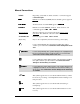
Manual Conventions Labels Dispensing system buttons, labels, switches or connections appear in this text style. %XWWRQV Fluidmove for Windows (FMW) buttons and dialog boxes appear in WKLV WH[W VW\OH. 0HQX 6HOHFWLRQV All menu selections within FMW appear in WKLV WH[W VW\OH. &RPPDQGV Fluidmove for DOS (FMDOS) windows, menu selections, and commands appear in WKLV WH[W VW\OH. Glossary Terms The first occurrence of a glossary term appears italicized and underlined.
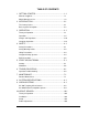
TABLE OF CONTENTS 1 GETTING STARTED........................................................... 1-1 Manuals Supplied ....................................................................... 1-1 Which Manuals to Use................................................................ 1-2 2 INTRODUCTION................................................................. 2-1 The Century Series..................................................................... 2-1 Basic System Description .............................
Operation ....................................................................................10-14 Minor Troubleshooting ................................................................10-15 HS-Series RTA Specifications.....................................................10-16 11 NEEDLE SENSOR .............................................................. 11-1 Operation ....................................................................................11-3 Setup ..........................................
Table of Figures Figure 2-1 Basic C-702 System....................................................... 2-3 Figure 2-2 C-708 with Options......................................................... 2-4 Figure 2-3 C-708 AICE .................................................................... 2-5 Figure 2-4 Basic Dispensing Area ................................................... 2-6 Figure 2-5 C-702 Rear View ............................................................
Table of Tables Table 2-1 Century Series System Configurations ........................... 2-2 Table 3-1 Power Switches ............................................................... 3-5 Table 3-2 Download Program Control Functions ............................ 3-6 Table 3-3 Motion Control Functions ................................................ 3-7 Table 3-4 System Status Control Functions .................................... 3-8 Table 3-5 System Status Color Indicators and Conditions..............
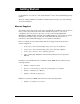
1 Getting Started Congratulations on your choice of an Asymtek Century Series Automated Fluid Dispensing System! TM This section helps familiarize you with the material that arrived with your system and helps use the documentation. Manuals Supplied Your Century Series dispensing system arrives with manuals for installation and operation of major system components and software. These manuals are specific to your system configuration.
Which Manuals to Use Below is a guide to when each manual will be most useful to you. The level of the intended user is also indicated. For Installation or Upgrading To install, reinstall or upgrade components of your system, refer to the Installation Manual. This manual may also be packaged in the Service Manual.
2 Introduction The Century Series Century Series systems are designed for a wide range of industrial and electronic applications. The Century Series family currently includes the C-702, C-708, and C-708 AICE.
Table 2-1 Model Application C-702 Century Series System Configurations C-708 C-708 AICE • Die attach • Die attach • Die attach • Surface mount adhesive • Surface mount adhesive • surface mount adhesive • IC encapsulation • IC encapsulation • IC encapsulation • Solder paste • Solder paste • solder paste • Gasket and electronic module sealing • Gasket and electronic module sealing • gasket and electronic module sealing • underfill Heating Type Valve Type Dispensing Area 2-2 • Needle He
Basic System Description Figure 2-1 through Figure 2-6 display several models, views and features of the Century Series systems. The callouts locate all major components, options, Control Panels and switches seen from that view. Paragraphs following the views provide brief explanations.
Additional Valve Pressure Gauge for Second Valve HT-2000 Dual Heater Controller for Needle Heater and Vacuum Heated Tooling Plate Light Pole/Beacon Additional Fluid Pressure Gauge for Second Valve Vacuum Generator for Tooling Plate Computer, Monitor and Keyboard Needle Sensor Light Curtain (right side receiver) Vacuum Heated Tooling Plate Dual-Action Dispensing Head Light Curtain (left side sender) Figure 2-2 2-4 C-708 with Options Introduction
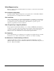
Light Pole/Beacon AV-2550 Vision System Dual-Action Dispensing Head (option) Needle Sensor Purge Station Vacuum Switch Swing arm Monitor Stand Slide-out Keyboard Shelf Vacuum Heated Tooling Plate Workstation Century AICE Figure 2-3 Introduction C-708 AICE 2-5
Dispenser Needle Sensor AV-700 Vision System Tooling Fixtures Height Sensor Valve or Fluid Pump (DV-6000 shown) Figure 2-4 2-6 Tooling Plate Basic Dispensing Area Introduction
Front View Features Below are short descriptions of the various parts and modules of the system (shown in Figure 2-1 through Figure 2-4) and their functions. Detailed operation instructions, for some features, are covered in other sections. Control Panel The Control Panel is an ergonomic membrane panel. It controls all programming and run functions and is divided into three functional areas: Downloading Program Control, Motion Control, and Safety Interlock Control.
Height Sensor The Height Sensor is installed on the Dispenser next to the fluid pump or valve. It checks and records the substrate height. Height Sensor operations are programmed using the dispensing system software. The Height Sensor is an option on the C-702 and C-708 and is standard on the C-708 AICE systems. HT-2000 Temperature Controller The HT-2000 is a precise temperature controller used to adjust the Vacuum Heated Tooling Plate and Needle Heater temperatures.
Power Switch The Power Switch on the front of the system is used to turn the system power ON. Purge Station This station consists of a small reservoir containing a disposable plastic cup. The system has a generator that can produce a vacuum inside the reservoir. The dispensing needle is inserted into the top of the Purge Station lid where the vacuum removes residual fluid and cleans the needle tip. The Purge Station is an option on the C-702 and C-708 and is standard on the C-708 AICE systems.
Rear Views Air Filter Shroud Main Air In High Air Pressure Relief Valve ! Cooling Fan Main Power Switch Main Power Cord Figure 2-5 2-10 CB-01 Cable Connection C-702 Rear View Introduction
. Hour Meter ! Expanded I/O Ports A, B and C CB-01 Cable Connection Figure 2-6 Introduction C-708 Rear View with Options 2-11
Rear View Features Below are short descriptions of the various parts and modules of the systems and their functions. Air Filter This filters out particles and impurities in the facility air supply. CB-01 Cable This cable connects to the RS-232C serial port of the Century Series system. Cooling Fan The fan is designed to cool the inside dispensing area. Expanded I/O Ports A, B and C These ports allow additional I/O access for adding options to the Century Series system.
Z-Axis Connector Z-Axis Fuse Expanded I/O Ports Connector Air Supply Connectors Power Entry Module Valve Cable Connector Safety Interlock Cable Connector Main Power Inlet Figure 2-7 Introduction RS-232C Cable Connector C-702/C-708 Rear Panel Connectors 2-13
C-702/C-708 Series Connectors This section briefly describes each connector and its function within the system. Only service technicians should access the connectors, fuses and electrical connections underneath the shroud. If you need access to the connectors, consult the Century Series Service Manual. If you have the Vision System option, two Vision System cables will extend from the Rear Shroud to connect to the computer.
3 Operation 127( Section 4 – Safety must be read along with this section before operating the system. Theory of Operation Century Series Systems are streamlined, easy to use machines that offer a wide range of flexibility while maintaining quality dispensing performance. Figure 3-1 and Figure 3-2 illustrate typical operation activity for the two main modes of operation: Programming Mode and Production Mode. In these operation examples, all configurations are considered and included.
P R O G R A M M IN G M O D E 6WDUW )OXLGPRYH /RDG 3DUW 6HFXUH 3DUW /RDG 2OG &UHDWH 1HZ 3URJUDP 3URJUDP 6TXDUH :RUN $OLJQ )LGXFLDOV 3LHFH (GLW 'LVSHQVLQJ $OLJQ )LGXFLDOV 3DWWHUQ $V 1HHGHG 7HDFK )LGXFLDOV ,I QR +HLJKW 6HQVRU 6HW 'LVSHQVH 6DYH 3URJUDP +HLJKW 5RXWLQH ,I QR 1HHGOH 6HQVRU )LQG 1HHGOH 'LVSHQVLQJ 3URJUDP 3DWWHUQ 6HW 8S $GMXVW 'LVSHQVLQJ 3DUDPHWHUV 6DYH 3URJUDP Figure 3-1 3-2 Programming Mode Operation
PRODUCTION MODE 6WDUW )OXLGPRYH 3DUW 0DQXDOO\ 3ODFHG RQ 7RROLQJ 3ODWH 1R &RPSXWHU $WWDFKHG &RPSXWHU $WWDFKHG 6HOHFW 'LVSHQVLQJ 3URJUDP IURP &RQWURO 3DQHO /RDG 'LVSHQVLQJ 3URJUDP 6WDUW 'LVSHQVLQJ 3URJUDP IURP &RQWURO 3DQHO 5XQ 'LVSHQVLQJ 3URJUDP $OLJQ )LGXFLDOV ,I QR +HLJKW 6HQVRU $OLJQ )LGXFLDOV 6HW 'LVSHQVH +HLJKW 5RXWLQH ,I QR +HLJKW 6HQVRU 6HW 'LVSHQVH +HLJKW 5RXWLQH ,I QR 1HHGOH 6HQVRU ,I QR 1HHGOH 6HQVRU )LQG 1HHGOH )LQG 1HHGOH 5XQ 3URJUDP 5XQ 3URJUDP Figure 3-2 Operation Production M
Operation There are several operation controls and indicators for the dispensing system components. This section will explain the operational use of these controls in detail. For special operation procedures, adjustments or maintenance of options and some major components, refer to the section of this manual dedicated to that option. Control Panels and Switches Figure 3-3 and Figure 3-4 identify the Control Panel functions and Power Switch.
Additional Fluid Pressure Gauge for Second Valve Figure 3-4 Additional Valve Pressure Gauge for Second Valve Century Series Control Panel with Dual Gauges Switches Table 3-1 Switch Power Switches Function This Power Switch, on the Control Panel, supplies power to the major system components. The , position is ON. The 2 position is OFF. 0 :$51,1* Operation The Main Power Switch (and Main Power Cord) supplies power to the Power Manager, which in turn supplies power to the entire system.
Control Panel The Control Panel is divided into three functional areas: • Download Program Controls • Motion Controls • System Status/Safety Interlock Controls The following tables describe each Control Panel function. Table 3-2 Button/Indicator Download Program Control Functions Function These are the Download Program Controls. The LED indicators numbered 0-9 indicate dispensing programs that have been saved in the dispensing system memory.
Table 3-3 Motion Control Functions Button/Indicator Function The X/Y-Axis Controls. (left/right) TEACH • The left and right arrow buttons move the dispense head to the left or right (X-Axis). • The up arrow moves the dispense head to the rear of the dispensing area (Y-Axis). • The down arrow moves the dispense head to the front of the dispensing area (Y-Axis). • The single arrow buttons move the dispensing head 25.4 mm/sec (1 in/sec).
Table 3-4 Button/Indicator System Status Control Functions Function IN T E R LO C K R E C O V E RY IN T E R LO C K The Safety Interlock is a key activated safety feature that can be used to restrict access to the inside of the dispensing area. For more information on the Safety Interlock, see Section 4 - Safety. SYSTEM STATUS SYSTEM STATUS LED indicators are color coded to reflect different SYSTEM STATUS conditions. For an explanation of the different status conditions, see Table 3-5.
Table 3-5 Indicator Color System Status Color Indicators and Conditions System Status ALERT A. or B. 1. Close doors, or change Interlock to . One of the following conditions exists: 2. Press SYSTEM RESET. A. 3. Press FIND HOME. 4. Select the proper Interlock mode for your application. 5. Restart the program. All motion, outputs, valves and motion controls are disabled. RED Recovery B. Doors open when system is moving, Interlock at ,. System is in an abort state.
Gauges and Regulators See Figure 2-1 and Figure 2-3 for the location of the Fluid Pressure Gauges and the Valve Pressure Gauges on the front panel. To reach the Regulator Controls, you must open the front doors or reach through the Light Curtain and reach below and behind the Control Panel as shown in Figure 2-1 or Figure 2-3. Refer to detailed adjustment instructions following the gauge and regulator descriptions.
Adjusting Air Pressures During dispensing operations, you can adjust valve and/or fluid air pressures to improve dispensing performances. Set the Main Air In (if your Century Series System has this regulator) to a value that is 69 kPa (10 psi) higher than the highest pressure you will use during dispensing operations. 7,3 To adjust the air pressure for valve and fluid pressure: 1. Make certain the dispensing system is ON.
Computer Operation The computer can be left attached to the dispensing system or can be removed if using FMDOS. You can leave the computer ON between dispensing operations. If using FMW, the computer must remain attached to the Century Series System. To clear computer system errors, it may be necessary to reboot the computer. Dispensing will stop automatically if you reboot or turn off your computer while you are running the dispensing program directly from the computer. To reboot the computer: 1.
4 Safety Your Century Series system has been designed to provide both safe and reliable dispensing operations. This section includes an explanation of the safety features and necessary precautions to ensure safe operation of the Century Series system. Safety Precautions Please review the following list of safety precautions for the operator and dispensing System before operating your Century Series system.
Safety Warning Labels To ensure the safety of all personnel, always observe standard safety precautions and practices. Before using your Century Series system, take a moment to familiarize yourself with the system safety features and warning labels. There are three different types of warning labels: Mechanical Mechanical warning labels identify features that require special attention.
! Figure 4-1 Safety Location of Safety Warning Labels 4-3
Lifting Precautions If you need to move a Century Series system at any time, call a service technician. See the Installation or Service Manual for instructions on moving the system. Failure to follow the Installation Manual instructions for lifting a Century Series system could cause serious bodily harm and/or damage the system. :$51,1* Integrated Safety Systems Your Century Series system offers the safety features described below.
Table 4-1 shows the Safety Interlock positions and corresponding modes of operation.
Emergency Shutdown In case of an emergency or malfunction, push E-Stop (see Figure 2-1). E-Stop cuts power to all system components. Generally, all system components are connected to the E-Stop outlet except the computer system, monitor, Vision System and Needle Heater. Emergency Shutdown Situations All Asymtek dispensing systems are designed to provide the highest level of safety under normal operating conditions.
Electrical Power Electrical power is supplied to the system through the Main Power Cord. The Main Power Cord connects the facility AC power source to the Main Power Inlet located on the back of the Century Series system (see Figure 2-5). All personnel working on or around the Century Series system should be aware of all electrical power supply sources. To turn the Main Power ON or OFF, use the Main Power Switch located on the back of the Century Series system (see Figure 2-5).
ESD Precautions Electrostatic Discharge (ESD), also known as “static discharge”, is the sudden transfer of electricity from one object to another (including people and tools). ESD can cause severe, unnoticeable damage to electronic printed circuit assemblies (PCA), parts and assemblies. Proper precautions must be taken to prevent the transfer of ESD damage while you are handling sensitive components.
5 Start-up/Shutdown This section guides you through simple start-up/shutdown procedures as well as providing recommended shutdown procedures at the end of production shifts and for servicing the Century Series system. Startup For startup procedures, refer to Figure 2-1 through Figure 2-7 to identify and locate parts and components. The green system status light on the Control Panel indicates when your Century Series system is ready to operate.
Operator Start Up in FMW Start up after a production shutdown: This procedure is for operators who will run a dispensing program. 1. Press the Main Power Switch on the back of the system to ON (,). 2. Press the Power Switch on the Control Panel to ON (,). 3. Press the Power Switch on the computer and monitor to ON (,). 4. Close all other programs. 5. Locate the FMW Program Group. 6. Double click on the FMW icon to start FMW.
Operator Start Up in FMDOS Start up after a production shutdown: 1. Press the Main Power Switch on the back of the Century Series system to ON (,). 2. Press the Power Switch on the Control Panel to ON (,). 3. Choose whether you will run your program from Download or from an attached computer and perform either Steps 4–5, or Steps 6–9. 4. To Download a program, select the program using Program on the Control Panel. 5. Press START to begin the dispensing program. 6.
Programming Start Up in FMW This is a minimal procedure for beginning a programming session. A more detailed procedure is outlined in the Fluidmove for Windows User Guide. 1. Press the Main Power Switch, at the back of the Century Series system, to ON (,). 2. Press the Power Switch on the Control Panel ON (,). 3. Press the Power Switch on the computer and monitor ON (,). 4. Close all running programs except FMW. 5. Locate the FMW Program Group. 6. Double click on the FMW icon to start FMW.
Programming Start Up in FMDOS This is a minimal procedure to begin a programming session. A more detailed procedure is available in the Fluidmove Reference Manual. 1. Press the Main Power Switch on the back of the Century Series system to ON (,). 2. Press the Power Switch on the Control Panel to ON (,). 3. Press the Power Switch on the computer and monitor to ON (,). 4. Close all running programs except FMDOS.
Shutdown You can shut your Century Series system down due to an Emergency, a Production Shutdown at the end of a shift and for a Service Shutdown. Emergency Shutdown 1. Press E-Stop. (This only turns off power to the mechanics. A Needle Heater run by an HT-1000 or a computer and monitor attached to the Century Series system will remain on.) 2. Press the Main Power Switch on the rear of the Century Series system OFF (2) to completely power OFF the system.
Operator Shutdown/End of Shift in FMDOS The following are recommended procedures for a production shutdown. To shut down at the end of a shift: 1. Wait for the dispensing program to complete. 2. Press the Power Switch on the Control Panel OFF (2). 3. Remove workpieces from the dispensing area. 4. Remove the syringe from the dispense head. 5. Clean or purge your fluid pump, refer to your Valve or Fluid Pump manual.
Service Shutdown in FMDOS Use the following recommended procedures to shutdown the Century Series system for service or removal. This procedure is for service technicians only. To shut down for service: 1. Wait for the dispensing program to complete. 2. Press SYSTEM RESET or open the door to engage the Safety Interlock. 3. Remove workpieces from the dispensing area. 4. Remove the syringe from the dispense head. 5. Clean or purge your fluid pump, refer to your Valve or Fluid Pump manual. 6.
6 Troubleshooting If you experience difficulties operating your Century Series System, use this section to identify a possible solution to the problem. If you experience difficulties not listed in this section, or the suggested solution does not correct the problem, then contact Asymtek Technical Support. 127( Service technician, as referred to in Table 6-1, means a service technician at your facility. The operator should contact this person, as directed in the table.
Troubleshooting Use the table below to identify possible solutions to some common operator issues. Table 6-1 Troubleshooting Guide Symptom Recovery A. If the Needle Sensor is installed, select Download Program 6 (),1' 1(;7 1(('/() using Program. Press Start. 1. Machine dispenses in the wrong X, Y or Z location. B. If a Vision System is installed, go to 6HWXS and select &$0(5$ 2))6(7 352&('85(. Restart dispensing program. C.
Table 6-1 Troubleshooting Guide (Continued) Symptom Recovery A. Verify monitor cable is securely connected at the back of the computer. B. Ensure that the monitor power is ON. 4. Monitor or video image is missing. C. Reboot the computer. D. Should the problem persist, call a service technician. 5. Valve Status indicator light(s) is illuminated. A. Press VALVE RESET and restart the dispensing program. Should the failure persist, the likely cause of the problem is a stalled motor.
7 Maintenance Routine Maintenance Routine maintenance of your Century Series system can prevent part degradation and ensure high quality performance for every production run. There are several simple procedures you can perform on a regular basis to guarantee quality dispensing and optimize system performance. It is essential that you follow all safety warnings and consider all safety warning labels when performing these procedures.
Lubricating the X-Axis (For Dual-Action and C-708 AICE with Thomson Carriage Installed) Lubricating the X-Axis on a monthly basis will ensure smooth dispense head movement and prolong bearing life. The tools needed to perform this procedure are included in the Asymtek SK-LUBE Kit, which is supplied with your dispensing system. Use the grease gun included in the Asymtek Kit to perform the following procedure: To lubricate the X-Axis: 1. Load the grease cartridge into the grease gun. 2.
17. Pump the grease gun once or twice to inject an ample amount of grease into the housing. ! When grease exudes from the end of the housing it is full. 18. Clean and wipe the X-Axis guide rods using an ammonia-based cleaner. 19. Repeat Steps 15–17 for the rear of the bearing housing.
8 System Specifications System Specifications This section lists the electrical and physical specifications for current Century Series Automated Fluid Dispensing Systems. Century Specifications Drive System X/Y-Axes Speed: Control: System Repeatability: System Resolution: Placement Accuracy: 508 mm/s (20 in/s) Brushless DC stepper motor ±0.025 mm (0.001 in) ±0.025 mm (0.001 in) ±0.13 mm (0.005 in) Z-Axis Speed: System Repeatability: System Resolution: System Specifications 203 mm/s (8 in/s) ±0.
Dispensing Area Dimensions* System NS-Series AV-700 VHP-01 DA-700 Dispensing Area 304 x 304 mm (12 x 12 in.) C-702 X X 304 x 273 mm (12 x 10.78 in.) X 241 x 287 mm (9.50 x 11.33in.) X 241 x 256 mm (9.50 x 10.11 in.) X 259 x 304 mm (10.21 x 12 in.) X 259 x 273 mm (10.21 x 10.78 in.) X X 225 x 304 mm (8.87 x 12 in.) X X 225 x 273 mm (8.87 x 10.78 in.) X X X X X X X 210 x 284 mm (8.27 x 11.21 in.) X 210 x 252 mm (8.27 x 9.93 in.) X 210 x 221 mm (8.27 x 8.72 in.) X 210 x 272 mm (8.
Fluid Delivery Method Supported by all standard Asymtek valves Dispensing Performance (Measured with dots of surface 15,000 dots per hour, 1.0 mm grid 13,750 dots per hour, 2.0 mm grid 12,000 dots per hour, 5.
9 Vision Systems Asymtek offers two vision systems for many of its dispensing systems. The AV-700 Targeting Offset Camera is our basic vision system equipped with standard configuration. The AV-2550 Pattern Recognition System (PRS) is an advanced vision system with a choice of light sources to accommodate edge detection and fiducial detection. This section describes the operation of these vision systems.
AV-700 Targeting Offset Camera The AV-700 displays a video image of your workpiece on the computer monitor while you are running Fluidmove software. When you program using the AV-700, the camera magnifies the workpiece and the video overlays crosshairs on the image to allow you to easily locate XY locations for accurate dispensing pattern placement. The AV-700 operates with Fluidmove software and in Download Mode.
Operation Controls To operate the AV-700 while programming in FMDOS: 1. Start the dispensing system. 2. Start Fluidmove. 3. Install your workpiece in the dispensing area. 4. To teach a dispensing pattern starting point, position the crosshairs over the center of the point. 5. Press [F9] to toggle between Fluidmove and the fiducial video image display on the monitor as necessary while programming. ! Many FMDOS commands will automatically display the video. 6. Press [Enter].
Operation in Download Mode When using the AV-700 in Download Mode on the dispensing system, the camera and light are turned ON with the dispensing system. The magnified workpiece image and crosshair are displayed as a full-screen image on command. Control Panel buttons are used to activate a program from Download memory. The operator uses the Arrow Buttons on the control panel to align programmed patterns and teach them to the dispensing system. To operate the AV-700 in Download Mode in FMDOS: 1.
Adjustments for the AV-700 The camera and built-in light ring on the AV-700 may require adjustments to the focus and the brightness. There are separate procedures for FMW and FMDOS. To adjust the focus using FMW: 1. Using a 5/64 inch hex key, loosen the setscrews holding the camera in place. 2. Move the camera up or down until the displayed image is in focus. 3. When satisfied, tighten the set screws to secure the camera. 4. In the FMW Main Window, click on &RQILJXUDWLRQ. 5. Select 1HHGOH 6HWXS. 6.
7. Select '21( if you are satisfied with the camera offset. If you select '21(, Fluidmove automatically begins the Needle Sensor Setup procedure. To perform a Needle Sensor Setup procedure without first performing a Camera Offset, simply select 6(7 1(('/( 6(1625 from the Setup menu. 127( Read the initial instructions displayed on-screen preceding this procedure before continuing. 8.
Minor Troubleshooting There are some troubleshooting procedures that an operator may perform. These are listed in the table below. Some problems that appear to be problems with the vision system may actually have other causes. Refer unsolved problems to a service technician. Table 9 -2 Troubleshooting Guide for the AV-700 Symptom Check/Correction • Make certain that the lens cap has been removed from the camera. • Check the camera cable harness connection to the back of the dispensing head.
AV-700 Specifications Computer Desktop computer with Pentium processor and 356 mm (14 in) SVGA monitor Field of View Size A-400 Series Benchtop 10.4 x 7.8 mm (0.41 x 0.31 in) A-400 Series Gantry 11.0 x 8.4 mm (0.43 x 0.33 in) A-600 Series 11.0 x 8.4 mm (0.43 x 0.33 in) Century Series Call Asymtek Technical Support* * Depends on dispensing area options. Power Universal voltage output 47-63 Hz 30-40 W (typical), 150 W (maximum) Working Envelope A-400/A-600 Series 12 x 12 in.
Camera A-400 Series Benchtop 25 mm lens, adjustable f-stop, clearance 78 mm (3.06 in) A-400 Series Gantry 25 mm lens, adjustable f-stop, clearance 43 mm (1.7 in) Century Series 25 mm lens, adjustable f-stop, clearance 43 mm (1.7 in) A-600 Series 25 mm lens, adjustable f-stop, clearance 43 mm (1.7 in) Focal length 43 mm (1.7 in) Focus Height Range See Table 9 –3 and Figure 9 –2. Table 9 –3 Model Century Series Focus Height Range Max. Assembly + Component Height (A)* 129 mm (5.08 in) See Note 1.
Camera Adjustable Camera Height Workpiece Focal Length Maximum Component Assembly Height (including fixture) Maximum Component Height B A Tooling Fixture or Conveyor Rails Figure 9 –2 9-10 Focus Height Ranges Vision Systems
AV-2550 Pattern Recognition System The AV-2550 Pattern Recognition System (PRS) magnifies the workpiece and displays it on the computer monitor. The AV-2550 can be used with either FMW or FMDOS. The AV-2550 has a Cognex® Vision Processor in addition to all of the same hardware as the AV-700 described above. This vision processor can recognize certain shapes, called fiducials, on the part or substrate and can be “taught” to recognize them on other parts for quick, accurate pattern placement.
Operation The sections below are an overview of the hardware operation of the AV-2550 system. Theory of Operation Refer to Figure 9 –3. The camera turns ON and the image is processed through the Cognex Vision Processor and is displayed on the monitor. The camera generates a crosshair over the image. The crosshair is calibrated to the XY location using a Fluidmove setup routine. After calibration, the dispensing head, camera and light ring are moved to a fiducial location on a workpiece.
Adjustments for the AV-2550 For controlling these features in FMW, refer to on-line Help. In FMDOS, you can control light levels in the &$/,%5$7( &$0(5$ routine within Cognex. Use [+] or [-] to increase or decrease light levels. Refer to Fluidmove DOS 3.3 Addendum: AV-2550 Automatic Fiducial Locating System for more detail. Minor Troubleshooting Vision Systems ! If the program freezes, reboot the computer and avoid using [Esc] or [Enter] while in a Cognex menu.
AV-2550 Specifications Computer Pentium computer with 356 mm (14 in) SVGA monitor Field of View Size A-400 Series Benchtop 10.4 x 7.9 mm (0.41 x 0.31 in) A-400 Series Gantry 10.9 x 8.4 mm (0.43. x 0.33 in) A-600 Series 10.9 x 8.4 mm (0.43. x 0.33 in) Millennium Series Call Asymtek Technical Support* Century Series Call Asymtek Technical Support* * Depends on dispensing area options. Working Envelope A-400/A-600 Series 12 x 12 in. systems 254 x 305 mm (10 x 12 in) 18 x 18 in.
Camera A-400 Series Benchtop 25 mm lens, adjustable f-stop, clearance 78 mm (3.06 in) A-400 Series Gantry 25 mm lens, adjustable f-stop, clearance 43 mm (1.7 in) Century Series 25 mm lens, adjustable f-stop, clearance 43 mm (1.7 in) A-600 Series 25 mm lens, adjustable f-stop, clearance 43 mm (1.7 in) Millennium Series 25 mm lens, adjustable f-stop, clearance 43 mm (1.7 in) Focal length 43 mm (1.70 in) Focus Height Range See Figure 9 –2.
10 Height Sensor The Retractable Adjustable Height Sensor (HS-Series RTA) is located on the dispensing head next to the needle. It checks and records substrate height to help maintain consistent dispensing height on a non-level or warped substrate. Consistent dispensing height is essential to ensure consistent dispensing quality. If your system includes this option, it should have been installed at the Asymtek factory prior to shipping.
Theory of Operation The Height Sensor uses a 1.58 mm (0.0625 in) diameter stainless steel probe to contact the dispensing surface. The probe tip is machined to a 0.51 mm (0.02 in) circle for minimum surface contact. Approximately 5 grams (0.18 oz) of contact force is exerted during a substrate height measurement. The low force eliminates substrate flex and vibration caused by probing and reduces placement inaccuracy and damage to delicate substrates.
Power Cord Valve or Fluid Pump (DV-06 shown) Height Sensor Bracket Spacer (used with DV-01, DV-02, DV-06 and DV-07 valves) Valve Bracket Figure 10-2 Height Sensor Height Sensor Installation 10-3
Setup Before performing any dispensing programs with the Height Sensor, make sure that the Height Sensor is properly set up. To set up the Height Sensor, use your dispensing software to run a Height Sensor Setup procedure. During the Height Sensor Setup process, you can assign values to control various Height Sensor parameters.
5. Click on &RQILJXUDWLRQ again. 6. Select 1HHGOH 6HWXS from the drop down menu. 7. Select &DOFXODWH 0DVWHU 2IIVHWV. 8. Follow the on-screen prompts. Consult on-line Help for assistance, if necessary. 7,3 Height Sensor We recommend that you perform this height sensor setup every time you make adjustments to the Height Sensor. If your change the needle, perform a )LQG 1HHGOH ;<= procedure instead of the Height Sensor Setup. )LQG 1HHGOH ;<= is found on the 6HWXS menu in the Programming Window.
Height Sensor Setup using FMDOS 1. On the FMDOS Main Program menu, select )LOH. 2. Press [Enter]. 3. Select 5XQ &RQILJXUDWLRQ. 4. Press [Enter]. 5. Answer “
Always Mode does not compensate for Z-height with the needle sensor. Selective Mode increases the processing time to the dispensing head. 7,3 16. Press [Enter]. 17. Answer “Yes” if asked the question “(QDEOH '27 = RIIVHW ZLWK ]IDVW"” 18. Press [Enter]. 19. Select 6HWXS = from the $XWRPRYH menu. 20. Select 6HW = +HLJKWV. 21. Set the = 5HWUDFW +HLJKW to 0.12. This setting should be satisfactory for most dispensing applications. However, you may need to experiment with this value. 22.
7,3 10-8 We recommend that you perform the height sensor setup every time you make adjustments to the height sensor. If your system is equipped with a Needle Sensor, then perform a )LQG 1H[W 1HHGOH procedure instead of the Height Sensor Setup after changing needles. )LQG 1H[W 1HHGOH is found on the 5XQ menu in the Main Programming Window.
Probe Adjustments Depending on the dispensing pattern, the substrate material, and/or the needle size, you may need to adjust the probe height in relation to the needle height, the distance between the probe tip and the needle tip, or the stroke length of the up and down motion of the probe. These adjustments can improve throughput and dispensing quality. Before attempting any of these adjustments, consult a service technician.
To make large-scale adjustments to the probe tip height: Only a trained service technician should perform this procedure. &$87,21 1. Raise the dispensing head so that neither the needle tip nor the probe tip are touching the work surface. 2. Using the 1/16 inch hex key, loosen the probe set screw accessed through the hole on the right side of the Height Sensor (see Figure 10-1). 3. Adjust the probe height by sliding the probe up or down (see Figure 10-3).
To adjust the distance between the probe and the needle: &$87,21 Only a trained service technician should perform this procedure. 1. Raise the dispensing head so that neither the needle tip nor the probe tip are touching the work surface. 2. Install the needle you will use. 3. Using the 1/16 inch hex key, loosen the probe set screw accessed through the hole on the right side of the Height Sensor (see Figure 10-1). 4. Move the probe to the new distance from the needle.
3. 4. Using the 1/16 inch hex key, turn the FU adjust screw to adjust the GU stroke length. ! To reduce the stroke length, turn the GU adjust screw to the left. ! To increase the stroke length, turn the GU adjust screw to the right. Go to the Terminal Mode Window by selecting 7HUPLQDO from the Fluidmove 5XQ menu in FMDOS, or by clicking on 7RROV in the FMW Main Window, then clicking on 7HUPLQDO and clicking on 'LVSHQVHU. 5.
To adjust the Z-Axis velocity and acceleration: The Z-Axis velocity and acceleration control the speed and acceleration of the lowering and raising of the dispensing head during a height sense measurement. Adjusting the Z-Axis velocity and acceleration can improve throughput by decreasing the amount of time it takes to make a height sense measurement. In FMW: 1. In the FMW Main Window, click on &RQILJXUDWLRQ. 2. Select 6HWXS +HLJKW 6HQVRU. ! The Height Sensor Setup dialog box opens. 3.
Operation Setup selections in FMW or FMDOS control Height Sensor operation. You can also insert additional height sense commands directly into dispensing programs. When not taking a height sense measurement, the Height Sensor probe remains in the retracted position to prevent it from interfering with the dispensing process.
Minor Troubleshooting Table 10 -1 Symptom HS-Series RTA Troubleshooting Check Correction • Perform a Calculate Master Offsets in FMW or a Height Sensor Setup in FMDOS. Check probe function: 1. Probe does not drop 2. Needle hits substrate ! Push the probe up with your finger. • ! If the green LED light on the side does not go ON, the probe is not working. Check to see if the LED is working by pushing the probe tip up. • Check if HS phone jack is connected to the dispensing head.
HS-Series RTA Specifications Height Compensation Accuracy: Z-Axis Velocity Z-Axis Acceleration 2 100 mm/sec (4 in/sec)** 2 7.5 m/sec (300 in/sec )** Repeatability ± 0.051 mm 3 sigma (± 0.002 in 3 sigma) 2 2 7.5 m/sec (300 in/sec )** 50 mm/sec (2 in/sec)** ± 0.038 mm 3 sigma (± 0.0015 in 3 sigma) 2 2 2.5 m/sec (100 in/sec )** 25 mm/sec (1 in/sec)** ± 0.026 mm 3 sigma (± 0.001 in 3 sigma) Force: 5 grams (0.18 oz) Probe Diameter: 0.51 mm (0.02 in) Probe Retract: Adjustable 5-10 mm (0.2-0.
11 Needle Sensor The Needle Sensor can be installed at various locations around the dispensing area, depending on the model of dispensing system. There are two types of Needle Sensors currently available. Millennium Series dispensing systems use either type of Needle Sensor. Century Series and other dispensing systems use only the NS Series. The NS Series is shown in Figure 11-1. The NSZ Series, which includes an accessory Load Cell for performing height sense tests, is shown in Figure 11-2.
The NSZ Series Needle Sensor includes a Load Cell, which is used to calculate the Z-height of the needle tip during the Calculate Master Offsets routine in FMW. Both types of Needle Sensors use a fiber optic LED infrared sensor to locate and record the XYZ location of the needle. The Needle Sensor is also used to determine the XYZ location of the Height Sensor Probe in relation to the needle.
Operation The NS Series Needle Sensor works with both FMW and FMDOS. The NSZ Series Needle Sensor works only with FMW. The software on the dispensing system is configured at the Asymtek factory to work with either type of Needle Sensor. Theory of Operation The dispensing needle is inserted into the slot in the sensor and passed in front of two light beams, one for the X-Axis and one for the Y-Axis. When the needle breaks the beam, its location is recorded.
Setup The Needle Sensor is installed on your system at the factory. In addition, FMW and FMDOS are configured to work with your type of Needle Sensor. If you make significant changes to your system configuration, upgrade FMW or FMDOS, or if you are having trouble with Calculate Master Offsets, Find Needle XYZ or Find Next Needle routines, you need to perform the setup procedures below.
Find Needle XYZ Find Needle XYZ is performed during programming or production runs. This routine checks the XYZ location of the needle and returns the information to the software, which automatically makes any needed adjustments to the dispensing program. You can run this routine at anytime, or program it anywhere in a production run. To perform a Find Needle XYZ: 1. In the Programming Window, select 6HWXS. 2. Select )LQG 1HHGOH ;<=. 3. Follow the on-screen prompts.
Setup in FMDOS Only the NS Series Needle Sensor uses FMDOS. The software does not recognize the Load Cell on the NSZ Series. There are three different setup options available depending upon your application. They are described below. Option 3 is a Find Next Needle procedure that must be performed whenever a new needle is installed. Option 1 – To use the Needle Sensor while creating a new file in FMDOS: 1. Got to )LOH. 2. Select 1HZILOH 3.
Option 3 – To use the Needle Sensor to perform Find Next Needle from download*: *For Century Series, A-400 Series and A-600 Series systems only. Whenever a new needle is installed, there is a possibility that its position is not identical to that of the previous needle. Minor changes in needle location can result in inaccurate dispensing. After you install a new needle, perform a Find Next Needle routine to compensate for any change in needle location. 1.
Minor Troubleshooting Table 11 -1 Symptom 11-8 Troubleshooting Guide Possible Cause Recovery LED does not come ON during routine Needle Sensor malfunction Call a service technician LED is constantly ON Dust in the sensor Clean sensor slots with a soft cloth or by blowing air through them Needle jams too far into the needle sensor slot Height change beyond capability Rerun Needle Sensor Setup Needle-to-Height Sensor offset is inaccurate Fluid build-up on probe tip caused inaccurate Height Sen
12 Needle Heater The Needle Heater consists of a Temperature Controller and a Needle Heating Element that attaches to the dispensing needle. The Needle Heating Element is selected for compatibility with your valve or fluid pump (see Table 12-1). For Millennium Series and Century Series C-708 AICE dispensing systems, the Temperature Controller is an integrated feature which also controls the dispensing area heaters.
Table 12-1 Heating Element Heating Element Compatibility Guide Valve Compatibility HT-04 Asymtek DV-04 valve only HT-06 All Asymtek valves except DV-04 HT-10N :$51,1* &$87,21 All Asymtek valves using metal needles The Needle Heater and all Heating Elements should be installed by a service technician. If the dispensing system needs to be moved, the Needle Heater should be disconnected.
Figure 12-2 Figure 12-3 Needle Heater HT-06 HT-10N 12-3
O O O O ON/OFF Switch O O Control Panel Close-up Figure 12-4 12-4 HT-2000 Temperature Controller Needle Heater
Theory of Operation The Heating Element attaches to the needle or to valve tip, depending on the type of heating element used. The temperature is set with the Temperature Controller. In FMW, the temperature is set in Heater Control for Windows (HCW). In FMDOS, the temperature is set directly with the Temperature Controller. A thermocouple cable connects the Heating Element to the Temperature Controller, allowing the temperature controller to sense the Heating Element temperature.
Installation On Millennium Series systems, the Heating Element and Temperature Controller is installed at the Asymtek factory. For Century Series systems, you need to install the Heating Element and Temperature Controller. Consult the dispensing system installation manual and refer to those Temperature Controller installation procedures. If this manual is not available, follow the procedures below. :$51,1* Only a service technician should perform these installation procedures.
Figure 12-5 HT-06 on a DV-6000 Pump with Luer Lock Fitting Figure 12-6 Needle Heater HT-10N on a DV-6000 Pump 12-7
Operation Controls and Adjustments If you are using the Needle Heater on a Millennium Series system running FMW, all control of the Needle Heater is managed through the FMW accessory software, Heater Control for Windows (HCW). In most cases, the Needle Heater is setup for your application at the Asymtek factory. However, if you need to modify the setup, follow the instructions below. To setup the Needle Heater on a Millennium Series system: 1. Start FMW. 2. Click on 7RROV. 3.
To set the Needle Heater temperature: 1. Press INDEX on the Temperature Controller front panel until you see Set Point 1 (63 . 2. Using ▲▼, adjust the temperature in the Set Value (SV) display to the desired value. 3. When you reach the desired value, press ENTER. 4. Press INDEX to record the value and return to the main display. To change the display to Celsius or Fahrenheit: 1. Press ▲ and ENTER simultaneously for five seconds. ! The display will show 6(&r and a number from 1-4. 2.
Advanced Operation To further define the heating process for your specific applications, you may want to change the Temperature Controller PID values. Only an advanced operator, process engineer or service technician should perform this procedure. Also, please refer to the OEM Temperature Controller Manual (if available) accompanying your system before changing any values.
Autotune The Autotune feature of the Temperature Controller can select new PID values for you. Follow the procedure listed below. Consult the OEM Temperature Controller Manual (if available) for more detailed information. To use the Autotune feature: 1. 2.
13 Special Options Asymtek offers a wide range of special options for fine-tuning your dispensing applications. This section introduces you to the options that are currently available for Century Series systems. Expanded Opto-I/O The Expanded Opto-I/O option for your Century Series system provides a special cable to access 24 I/Os. The Century Series systems use 8-bit I/Os for normal operation of all system components.
Operation Opto-I/O is electrically isolated from the other components of the system. This is an important safety feature for preventing overloads. The three 36-pin connectors are Ports A, B and C. Port A is the default port during normal operation and does not need to be connected to any device if it is the only active port. Ports B and C can be activated as accessories are added. The cables are attached as needed.
To add a port change command to a dispensing program in FMDOS: 1. Start FMDOS. 2. Select /2$' ROG ILOHV. 3. Select ),/( from the menu bar. 4. Select /2$'. 5. Press [Enter]. 6. Press [Enter] again to view a list of all dispensing programs. 7. Select your dispensing program. 8. Select 3UHVV (6& IRU 0DLQ 0HQX. 9. Press [F2]. 10. Use the arrow keys to locate the desired line in your dispensing program to enter the ACL Command to change your Port. 11. Press [Esc]. 12. Select 352&(66. 13. Press [Enter]. 14.
To change a port in FMW: 1. Start FMW. 2. In the Main Window, click on &RQILJXUDWLRQ. 3. Select 6HWXS 6HULDO 3RUWV from the Configuration menu. ! The Serial Ports Setup dialog box opens. 4. Select the port assignment for each device. 5. Click on 2.. To add a port change command to a dispensing program in FMW: 1. Start FMW. 2. In the FMW Main Window, click on 7HDFK D 3URJUDP. 3. Select )LOH. 4. Open your dispensing program file. 5.
Applicable ACL Commands I/O ports are controlled with the following commands. The ACL Reference Manual (P/N 76-CS02-01, Rev. 3.7 and later) details these capabilities.
Interconnects The following table of interconnects can be used for testingdevices and I/Os. Normally, only trained service personnel use this table.
Light Curtain The Light Curtain is an optical sensor (see Figure 13-2) that is mounted inside the entrance of the dispensing area in place of doors. The sensor detects any object 14 mm (0.55 in) or larger that crosses the entrance and activates the Safety Interlock.
Theory of Operation The Light Curtain contains a photodiode array pair. Light from the Sender unit is detected by the Receiver unit. This creates a detection plane at the entrance of the dispensing area. When an object 14 mm (0.55 in) or larger crosses the plane, the light between the Light Curtain pair is disrupted. The fault is detected and all mechanical motion stops.
Indicator Status The LEDs on the lower inside edge of each Curtain Indicator reports the status of the Light Curtain system. The following table describes the Light Curtain status associated with each LED color. Table 13-3 Indicator Light Curtain Status Indicators LED Color Status Condition YELLOW Sender Sender is active and transmitting normally. Both the amber and yellow LEDs are ON during normal operation. Power ON. AMBER YELLOW AMBER Receiver RED GREEN Special Options Dirt has been detected.
Vacuum Heated Tooling Plate The Vacuum Heated Tooling Plate option holds a part on the tooling plate and supplies controlled heating underneath the part. This feature improves fluid flow control and dispensing accuracy. A silicone rubber-resistive element pad heats an aluminum tooling plate. The temperature of the tooling plate is controlled by FMW software and/or the HT-2000 Controller. (When using FMDOS, only the temperature controller can operate the heater.
O O O O O O Figure 13-4 HT-2000 Temperature Controller Theory of Operation The Vacuum Switch activates a Venturi-type generator that provides a vacuum to the part through the holes on the tooling plate. The Temperature Controller brings the temperature of the tooling plate to a preset temperature which then remains constant. Heat is applied by contact of the tooling plate to the part. The Vacuum Switch deactivates the vacuum and the part is removed from the dispensing area.
Vacuum Control In order for the vacuum to function properly, the facility air supplied to the Century Series system should be set to 600 kPa (87 psi). The vacuum generator is not user adjustable, the facility air should be set to the above pressure for optimum usage. To start the vacuum, use the Vacuum Activation Switch located on the front right side of the dispensing area (see Figure 13-3). Heating Plate Temperature Control The temperature is controlled by the HT-2000 Controller (see Figure 13-4).
To change the display to Celsius or Fahrenheit: 1. Press ▼ and ENTER simultaneously for five seconds. ! The display will show $ and a number from 1 to 4. 2. Press INDEX until 8QLW displays. 3. Use ▲▼ to toggle between Fahrenheit and Celsius. 4. Press ENTER to record the new unit. 5. Press ▼ and INDEX simultaneously until the primary menu displays.
Light Beacon The Light Beacon displays the same color code as the SYSTEM STATUS lights on the Control Panel. The Light Beacon is installed on the back of the dispensing system. It warns the operator both visually and audibly of the system status. Light Beacon Figure 13-5 Light Beacon Operation Controls Operation of the Light Beacon is automatic. The blue light on the Light Beacon can be configured to activate for a customer-specific system status.
Minor Troubleshooting The table below describes some symptoms that are easily corrected. For other problems, call a service technician. Table 13-4 Symptom Operator Troubleshooting Check/Correction No lights Check cable connections from the Light Beacon (see Table 13-1). Incorrect light illumination Check cable connections from the Light Beacon (see Table 13-1).
Low Air Pressure Sensor The Low Air Pressure Sensor attaches to the Main Air In connector. If pressure drops below a set point, it triggers the dispensing system Safety Interlock. This feature is used to alert the operator of pressure drop conditions that may occur in large facilities with a number of pneumatic devices requiring air.
Operation Controls If you need to change the Main Air pressure, refer to “Adjusting Air Pressures” in Section 3 – Operation. To set the low pressure valve to trigger the sensor, follow the instructions below. You need a flathead screwdriver to complete this adjustment. To set the low pressure set point: 1. Set the system pressure with the Valve Pressure or Fluid Pressure regulators to the low kPa (psi) at which you want to trigger the alarm.
Hour Meter The Hour Meter measures the operation time of the dispensing system. The operation time is the total time, idle or operating, that the dispensing system is ON. The Hour Meter attaches to the rear of the system (see Figure 13-7). Hour Meter ! Figure 13-7 Hour Meter Theory of Operation The Hour Meter connects to the dispensing system Power Manager. When the dispensing system is turned ON, power is supplied to the Hour Meter and it begins counting.
Glossary ACL: Abbreviation for Automove Control Language. Automatic Fiducial Locating System: A vision system that finds fiducials and compensates for small changes on a workpiece during dispensing. Automove Control Language: An Asymtek proprietary motion control language consisting of commands that control all components of the dispensing systems. Axis: X, Y or Z geometric dispensing coordinates. See Figure G-1. E-Stop: Emergency Stop button. Cuts power to the dispensing system only.
Non-Recoverable Interlock Condition: You must completely exit the dispensing software program, re-start the dispensing software and re-open the program to continue. Offset Camera: Camera that uses crosshairs in the Vision System to locate XYZ locations. Teach: Entering and saving XYZ locations. Valve: A device used to control the flow of fluid on dispensing systems. Workpieces: A dispensing target. X-axis: Left to right movement of the dispense head in the dispensing area.
Index A ACL commands, 13-5 air filter, 2-12 air pressure adjusting, 3-11 Relief Valve, 2-12, 4-7 applications, 2-1 G gauges and regulators, 3-10 fluid pressure, 2-7, 3-10 valve pressure, 2-9, 3-10 H B brightness adjustments, 9-6 C Calculate Master Offsets, 10-5, 10-15, 11-1, 11-4 camera calibrations, 9-13 CB-01 cable, 2-12 color codes, 3-9 computer system, 2-8, 3-12 connector(s) air supply, 2-14 expanded I/O ports, 2-14 grounding strap, 2-7 safety interlock cable, 2-14 valve cable, 2-14 Z-Axis, 2-14 con
heating elements, 12-6 setting temperature, 12-8 specifications, 12-12 thermocouples, 12-6 needle location, 11-3, 11-4, 11-7 Needle Sensor, 2-8, 11-1 cleaning, 11-8 load cell, 11-2 NS Series, 11-2 NSZ Series, 11-2 parameters, 11-5 setup, 9-5, 11-4 troubleshooting, 11-8 P pattern recognition, 9-1, 9-11 Power Entry Module, 2-14 Power Switch, 2-9 Process Value, 12-8, 13-12 programming, 5-5 purge station, 2-9 R RS-232C, 2-14 S Safety Interlock, 2-9, 4-4, 4-5 Light Curtain, 13-7 Safety Precautions, 4-1 Set Va