
Manual


Introduction 2-3
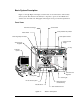
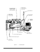
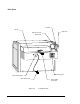
Basic System Description
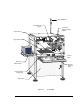
Figure 2-1 through Figure 2-6 display several models, views and features of the Century
Series systems. The callouts locate all major components, options, Control Panels and
switches seen from that view. Paragraphs following the views provide brief explanations.
Front Views
Figure 2-1 Basic C-702 System
Computer
System
Fluid Pressure
Regulator
Grounding Strap Connector
Power Switch
Fluid Pressure Gauge
C
ontrol Panel
Safety Interlock Key Switch
Valve Speed Controls
Valve Pressure
Gauge
E
-stop
Tooling Plate
AV-700 Vision System
Needle Sensor
D
oor Interlock Sensors
Dispensing Head
and Fluid Pump
Interior Light
V
alve Pressure
R
egulator