
Manual


Introduction 2-7
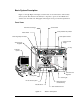
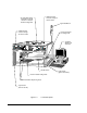
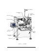
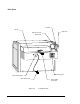
Front View Features
Below are short descriptions of the various parts and modules of the system (shown in
Figure 2-1 through Figure 2-4) and their functions. Detailed operation instructions, for some
features, are covered in other sections.
Control Panel
The Control Panel is an ergonomic membrane panel. It controls all programming and run
functions and is divided into three functional areas: Downloading Program Control, Motion
Control, and Safety Interlock Control. You can enable the Safety Interlock, make an
emergency stop, check system status and adjust pump controls from this panel.
Dispenser
The Dispenser moves the dispensing head up and down. The dispensing system software and
the Control Panel control the Dispenser. The Height Sensor, Needle Heater, if one is
installed, and the fluid pump are connected to the Dispenser.
E-Stop
In emergencies, this large “mushroom” button shuts down system power to the Control
Panel, the dispensing mechanics and the HT-2000 Temperature Controller, if equipped.
Fluid Pressure Gauge and Regulator
This gauge indicates the air pressure being supplied to the dispensing fluid reservoir or
syringe used with the fluid pump. Systems equipped with a Dual-Action Dispensing Head
will have an additional fluid pressure gauge for the second pump. The control regulator is
located just underneath the front hood of the system.
Fluid Pump
Century Series systems use a variety of fluid pumps or valves. The fluid pump or valve is
mounted on the Dispenser and holds the syringe of dispensing fluid and the needle.
Front Doors (not shown)
The front doors have an electrostatic dissipative surface that will not hold an electrostatic
charge. Door sensors connect the front doors to the Safety Interlock system.
Grounding Strap Connector
The operator’s grounding strap plugs into this connection to prevent Electrostatic
Discharge (ESD).