Asymtek Century Series Operations Manual The hardcopy part number for this manual is 196034, Revision A. The CD part number is 196035, Revision A. To reorder this manual, please contact Asymtek, 1-760-431-1919.
Revision History Revision Date A 5/01 Description Initial Release Pages Affected All
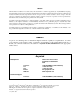
NOTICE All information contained in or disclosed by this document is considered proprietary by Asymtek. By accepting this material the recipient agrees that this material and the information contained therein are held in confidence and in trust and will not be used, reproduced in whole or in part, nor its contents revealed to others, except to meet the purpose for which it was delivered.
Manual Conventions Bold text indicates a menu selection, button selection, switch position, label, Bold Text computer command, filename, file location, internet address or other information that must be clicked on, typed or noted by the user. [Bracketed Text] [Bracketed Text] indicates a key to press or a keyboard sequence, such as [Enter] or [Alt + Tab]. WARNING! CAUTION! ? NOTE Safety Warning. This symbol will appear in a highlighted text block.
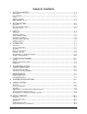
TABLE OF CONTENTS 1 GETTING STARTED ..............................................................................................1-1 Overview ..............................................................................................................................................1-1 System Status ......................................................................................................................................1-1 Safety ................................................................
Height Sensor Troubleshooting .......................................................................................................10-16 Specifications for HS Series RT.......................................................................................................10-17 11 NEEDLE SENSOR................................................................................................11-1 Overview ..........................................................................................................
Table of Figures Figure 2-1 C-721 Front View .................................................................................................................................... 2-2 Figure 2-2 Dispensing Area Close-up....................................................................................................................... 2-3 Figure 2-3 Lower Cabinet .........................................................................................................................................
1 Getting Started Congratulations on your choice of a Century C-721 Series Advanced IC Encapsulation dispensing system! Overview This manual is intended primarily as a reference for production operators. However, process engineers and service technicians unfamiliar with Asymtek products may also find this manual useful as a general introduction to the system.
Manuals Supplied Your Century Series dispensing system arrives with manuals for installation and operation of major system components and software. For some system components, you may receive Original Equipment Manufacturer (OEM) manuals. Generally, these OEM manuals are only needed for reference and advanced troubleshooting. Consult only Asymtek manuals unless directed to do otherwise by Asymtek Technical Support or by Asymtek documentation.
Which Manuals to Use Below is a guide to when each manual will be most useful to you. The level of the intended user is also indicated.
2 Introduction Overview The Century Series Advanced Integrated Circuit Encapsulation (AICE) systems are designed to solve the diverse needs of the emerging flip chip underfill and IC encapsulation market. The Century Series C-721 Dispensing System provides a modular approach to hardware, software, and factory integration.
System Front Views 3 4 2 1 5 Valve 2 Pressure Valve Pressure Fluid 2 Pressure DP2-42N 1MPa Fluid Pressure DP2-42N OUT1 OUT2 MODE 0 - ADJ 1MPa Abort OUT1 OUT2 MODE 0 - ADJ 0 SUNX 0 SUNX Pause 9 8 7 6 5 4 Program 3 2 1 Start 0 Z Axis Teach Conveyor Status Conveyor Pause Find Home Interlock Recovery Dispenser V1 Status Dispenser Valve Status Interlock Reset Reset DP2-42N Valve Reset OUT1 1MPa DP2-42N 1MPa OUT2 OUT1 OUT2 MODE MODE 0 - ADJ 0 SUNX 0 - ADJ 0 SUNX V2 Cen
3 4 5 6 7 2 1 15 16 17 8 14 13 Item 1 2 3 4 5 6 7 8 9 10 11 12 13 14 15 16 17 12 11 10 9 Description Fluid Pressure Regulator Fluid 2 Pressure Regulator Grounding Strap Connector Fluid Pump Syringe Valve Pressure Regulator Valve 2 Pressure Regulator Over-the-Board Sensor Amplifier Impingement Heat Flow Controls (shown), Two- or Three-Station Tooling Mode Switch (Impingement/OFF/Contact) Purge Station Needle Sensor Tactile Needle Sensor Over-the-Board Fiber Optic Sensor Stop Pin Contact Heate
4 1 3 2 Item 1 2 3 4 Description Computer System Temperature Controller, 4- or 8-Channel Heat Station Timers Conveyor Controller Module Figure 2-3 Lower Cabinet 2-4 Introduction
Front View Features Below are short descriptions of the various parts and modules of the system (shown in Figure 2-1 through Figure 2-3) and their functions. Detailed operational instructions for some of these features are treated in other sections. Computer System (computer, monitor, keyboard, mouse) The Computer System is used to create and run dispensing programs with the Asymtek dispensing software Fluidmove for Windows NT (FmNT).
Fluid Pump The fluid pump (also referred to as a “valve” or “jet”, depending on the type) dispenses the fluid onto the part. It is mounted on the Dispensing Head, and holds the syringe of dispensing fluid. For more information, see the appropriate fluid pump manual. Popular models include the DP-3000 Series Pump, DV-6000 Series Pump, DV-7000 Series Heli-flow pump, and DJ-2100 Series DispenseJet valve.
Purge Station The Purge Station is a small reservoir that contains a disposable plastic cup. A generator produces a vacuum inside the reservoir. The dispensing nozzle or needle is inserted into the purge boot on the purge station lid, where the vacuum removes residual fluid and cleans the nozzle or needle tip. Stop Pin Stop pins are pneumatic devices used to stop parts at each station.
System Rear View 7 8 3 4 1 5 6 2 Item 1 2 3 4 5 6 7 8 Description Main Power Circuit Breaker Main Power Inlet Ventilation Duct; diameter is 100 mm (3.
4 1 Item 1 2 3 4 2 3 Description Conveyor Air Gauge and Regulator Main Air Gauge and Regulator (t-bar) High Air Pressure Relief Valve Air Filter and Water Trap Figure 2-5 Rear View Close-Up Introduction 2-9
Rear View Features Below are short descriptions of the various parts and modules of the systems and their functions. Air Filter and Water Trap The Air Filter and Water Trap remove moisture and impurities from the facility air supply. Conveyor Air Gauge and Regulator The Conveyor Air Gauge indicates the air pressure supplied to the lift tables and stop pins on the conveyor. The Conveyor Air Regulator is located under the gauge. The recommended setting is 379 kPa (55 psi).
3 Safety Overview Your Century Series system is designed to be safe and reliable. This section describes the features and precautions needed to ensure safe operation of the Century Series system. Safety Precautions WARNING! Failure to comply with any of the safety recommendations below could cause serious bodily harm to the user. Please review the following list of safety precautions for the operator and dispensing system before operating your Century Series system.
System Protection Precautions 3-2 • Always wear a grounding strap and connect it to the ESD ground when operating the system. • Be especially careful when dispensing fluids that are caustic or conductive. Immediately clean up and contain all spills. If fluid gets into internal portions of the dispensing systems, call Asymtek Technical Support immediately. • Maintain a clean and orderly work area. • Follow all recommended system maintenance.
Safety Warning Labels WARNING! CAUTION! Follow all safety warning labels. Failure to comply could cause serious bodily harm to the user and serious damage to the dispensing system. To ensure the safety of all personnel, always observe standard safety precautions and practices. Before using your dispensing system, take a moment to familiarize yourself with the system safety features and warning labels. Table 3-1 shows the four types of warning labels used on the dispensing system.
4 3 5 2 7 6 1 Item 1 2 3 4 5 6 7 Description Electrical Warning (high-voltage electrical components inside) Thermal Warning (conveyor aperture) Mechanical Warning (conveyor aperture) Mechanical Warning (conveyor aperture) Thermal Warning (conveyor aperture) Thermal Warning (near part heaters) Thermal Warning (near part heaters) Figure 3-1 Warning Labels, Front View 3-4 Safety
1 2 3 Item 1 2 3 Description Thermal Warning (conveyor aperture) Mechanical Warning (conveyor aperture) Electrical Warning (high-voltage electrical components inside) Figure 3-2 Warning Labels, Rear View Safety 3-5
Emergency Shutdown WARNING! Failure to completely shut down power to the Century Series system in an emergency with EMO and the Main Power Circuit Breaker could cause serious bodily harm to the user and/or serious damage to the dispensing system. In case of an emergency or malfunction, push the Emergency Machine Off (EMO) button (see Figure 3-3 below). The EMO cuts power to all system components except the computer and monitor.
To recover after an Emergency Shutdown: NOTE If the Main Circuit Breaker has been tripped, you will need to switch it back ON (I) and execute standard startup procedure (see the Startup/Shutdown section). 1. Turn the EMO button counterclockwise until it pops back into position. 2. Clear the Conveyor of all boards and parts. 3. Remedy the cause of the emergency shutdown. 4. Press the green START button on the Control Panel. 5. Press Find Home on the Control Panel.
Integrated Safety Systems Your Century C-721 system offers the safety features described below. Safety Interlock System CAUTION! Do not use the Safety Interlock to stop the dispensing machine during normal operation. It is a built-in safety feature to prevent access to the dispensing area while the dispensing program is running. Opening the doors during dispensing may ruin the board.
To recover from a shutdown triggered by the interlock: 1. Close the doors. 2. On the Control Panel: a. Press Dispenser Status Reset. Wait three seconds. b. Press Find Home. 3. In FmNT, click on the GO button. Table 3-2 shows the two Interlock positions and corresponding modes of operation.
Table 3-3 Beacon Color Indications Panel / Beacon Color RED (Audible Alarm) YELLOW Dispensing Status ALERT All motion, outputs, fluid pump, and motion controls are disabled. One of the following conditions exists: A. Not Flashing – system in an E-stop condition. B. Not Flashing – Software driven error message displayed on computer monitor C. Custom-programmed condition has triggered red light. Recovery Procedures A. 1. Remedy anomaly causing the E-stop. 2. Reset EMO button. 3.
ESD Precautions Electrostatic Discharge (ESD), also known as “static discharge,” is the sudden transfer of electricity from one object to another (including people and tools). ESD can cause severe, undetectable damage to electronic parts and assemblies. Proper precautions must be taken to prevent the transfer of ESD damage while you are handling sensitive components.
Electrical Power Electrical Power is supplied to the dispensing system through the Main Power Inlet. The Main Power Cable connects the facility AC power source to the Main Power Inlet located on the rear of the Century Series system (Figure 3-5). WARNING! CAUTION! Lock out power when performing service or maintenance work on the dispensing system, be sure to lock out power (see “Locking Out Power” on page 3-13).
Locking Out Power To lock out the Century Series system: 1. Turn OFF (0) the Main Power Circuit Breaker. 2. Unplug the Main Power Cable from the facility source. 3. Lock Main Power cable in a locked box for safety. High Air Pressure Relief Valve Pressure of factory air supplied to the dispensing system may fluctuate. The High Air Pressure Relief Valve opens to relieve system air pressure if it exceeds 690 kPa (100 psi).
4 Operation Overview All Century Series systems work in accordance with the same theory of operation demonstrating the highly developed process control. The main differences in operation between Century Series models operations are in the operation of the part heaters and options. In this theory of operation, all configurations are considered and included. However, system operation for your specific application will vary with respect to part heaters and installed options.
Alternatively, the system can be programmed to move the part directly to a downstream machine or onto an unloader. Another part is loaded into the Dispense Zone and clamped in place. Dispensing on the second part begins. A third part is loaded into the Pre-dispense Zone. The part is heated (if Post-dispense Zone is present). If so programmed, the part heaters for the Post-dispense Zone heat the part to a pre-programmed temperature. The part exits the system.
SMEMA Handshaking with Upstream Machine Part Loaded Heating Option Stops at PreDispense Zone Second Part Enters System Does Not Stop at Pre-Dispense Zone Part Arrives at Dispense Zone Heating Option One or more of the following may occur: • Pump/Valve Purges • Vision System Activation • Performance of Height Sense Dispensing Begins Dispensing Concludes SMEMA Handshaking with Downstream Machine Heating Option Part Moves to Post-Dispense Zone Part Loaded Part Moves out of System Second Part Mo
Dispenser Operation There are several operation controls and indicators for the dispensing system components. This section explains the general operational use of these controls. Computer System The computer is located inside the lower cabinet. The CD-ROM drive, disk drive, power switch, and reset button are located on the faceplate of the computer. Access to connections in the rear of the computer should be limited to service technicians. The computer runs Fluidmove for Windows NT (FmNT).
Computer Faceplate Figure 4-2 shows the faceplate controls of a typical system computer. 1 2 3 A NORDSON COMPANY 5 4 Item 1 2 3 4 5 6 6 Description CD-ROM Drive 3.
Computer Features Below are short descriptions of the various parts of the computer system and their functions. CD-ROM Drive Press the button below and to the right of the disk tray to insert or eject a disk. Floppy Disk Drive The computer has at least one 3.5-inch, 1.4 MB disk drive. Insert a 3.5-inch disk through the drive door flap. Press the small button on the lower right to eject the disk. Hard Drive Activity Indicator This light blinks when the hard drive is active.
6. Read and act upon any screen prompts to continue the booting process. > Windows will restart. 7. Start FmNT by double clicking on the program icon. To turn ON the computer separately, while the dispensing system is ON: 1. Verify that the dispensing system is ON. The Light Beacon will show a blue, green, or yellow status light (for color descriptions see Table 4-6). > If the Light Beacon shows a red status light, see the Troubleshooting section of this manual. 2.
Control Panel and Switches Figure 4-3 identifies the Control Panel functions. See Table 4-1 through Table 4-5 for details about the functions.
EMO (Emergency Machine OFF) Table 4-1 EMO Button Button Function Located at the right end of the Control Panel, the large, red EMO (Emergency Machine OFF) button cuts electricity to the power manager and stops all system motion. EMO cuts power to all system components except the computer and the monitor. Switches WARNING! In an EMO-related emergency, you must turn the Main Power Circuit Breaker to OFF (0).
Control Panel The Control Panel is divided into three functional areas: • Download Program Controls • Motion Controls • Dispensing Status/Safety Interlock Controls The following tables describe each Control Panel function. Table 4-3 Download Program Control Functions Button/Indicator Function Abort halts a production run. After you press the Abort button, its red LED lights to indicate that the currently loaded program is discontinued.
Table 4-4 Motion Control Buttons Button/Indicator Function Z AXIS Z-Axis Controls (up/down) Operation • Click and release a single arrow to move Dispensing Head 0.025 mm (0.001 inches) • Click and hold single arrow to move Dispensing Head 25.4 mm per second (1 in/sec) • Click and hold double arrow to move Dispensing Head 50 to 75 mm per second (2 to 3 in/sec) TEACH TEACH lets you set the coordinates of a fiducial point, or other location on the dispensing surface, with FmNT.
Table 4-4 Motion Control Buttons (continued) Button/Indicator CONVEYOR 4-12 DISPENSER Function Conveyor controls (conveyor belt, conveyor width adjust) and Dispenser controls (XY-axis, left to right, front to rear) Press the Dispenser button to activate the Dispensing Head’s XY motion controls: • The left and right arrows move the Dispensing Head to the left or right (X-axis) • The up and down arrows move the Dispensing Head to the rear and front of the dispensing area (Y-axis) • Click and release
Table 4-5 Button/Indicator Dispensing Status Control Functions Function CONVEYOR STATUS PAUSE Conveyor Status has two buttons, Pause and Reset. Pause halts the conveyor, and its LED indicates that the conveyor has been paused. Press Pause again to resume conveyor movement. Reset clears the controller after its LED indicates that a fault condition has occurred.
Table 4-5 Button/Indicator V1 VALVE STATUS Dispensing Status Control Functions (continued) Function A Valve Status LED turns ON if there is a problem with the fluid pump motor. It usually indicates that the pump electronics (overcurrent protection circuitry) has detected a power surge. When the LED is ON, the valve is disabled. V1 is Valve 1. V2 is Valve 2. To recover, press the Valve Reset button. If the problem persists, the pump may need to be cleaned.
Light Beacon The light beacon is ON whenever the dispensing system is ON. It can serve as an audible warning device by issuing an alarm, or as a visual warning device, indicating different status conditions by turning on a different color light for each condition. There are four possible status colors. The associated system condition is indicated in Table 3-3, Beacon Color Indications. These conditions are associated primarily with the status of the front doors and the Interlock.
Gauges and Regulators The C-721 has four types of gauges and regulators: • Main Air • Fluid • Valve • Conveyor WARNING! Before you reach inside the dispensing system front doors, you must fully understand the related Dispenser Status indicators, which have the same meanings as the Beacon color indications in Table 3-3. The fluid and valve regulator controls are black knobs extending down from the roof of the dispensing area. To reach them you must open the front doors.
Main Air Inlet Located next to the air filter, the Main Air Inlet provides regulated air pressure to the dispensing system from your facility air source. You can adjust the main air pressure with the metal T-bar regulator (Figure 4-4). ? NOTE Recommended pressure from facility air to the dispensing system is 586 to 620 kPa (85 to 90 psi).
Fluid and Valve Fittings The pneumatic fittings for the fluid and valve pressure are located on the right side of the Dispensing Head (Figure 4-5).
3 2 4 1 5 Item 1 2 3 4 5 Description Clear Pneumatic Fitting (air pressure to syringe) Toggle Up (black) (used with optional dual-action Dispensing Head) Toggle Down (blue) (used with optional dual-action Dispensing Head) Black Pneumatic Fitting Blue Pneumatic Fitting Figure 4-5 Fluid and Valve Pneumatic Fittings (connections shown for DP-3000) Operation 4-19
Fluid Pressure The fluid pressure regulator controls the pressure of air from the Main Air Inlet to the clear pneumatic fitting located on the right side of the Dispensing Head. This fitting connects to the top of the syringe. The system maintains steady fluid pressure by applying air at a constant pressure to the syringe while the dispensing system is ON. For more details on how air pressure is used for fluid pump or valve operation, see the manual for your specific fluid pump.
Valve Pressure The valve pressure regulator controls the pressure of air from the Main Air Inlet through the air line that connects to the fluid pump. Air pressure pushes the fluid pump open and closed during dispensing. Your dispensing program controls the operation of the fluid pump while dispensing fluid. For more details on how air pressure is used for fluid pump operation, see the appropriate manual for your specific fluid pump.
To adjust the fluid pressure/valve pressure: 1. Verify that the dispensing system is ON. > The Dispenser Status LED and Light Beacon should be yellow or green. 2. Open the front doors. > The green Dispenser Status LED and Light Beacon will turn yellow. 3. Reach underneath the left side of the front hood of the dispensing system and pull the fluid pressure regulator down to unlock it. 4. Rotate the regulator counter-clockwise to set the fluid pressure to 0 kPa (0 psi). 5.
To set parameters for the digital gauge (see chart below): 1. The first digit sets the display mode to digital (d) or analog (A). Change its value by pressing the key. 2. To adjust the second and third digits, first press the adjust the selected digit by pressing the key until the desired digit blinks, then key according to Figure 4-9 below: Figure 4-9 Digital Pressure Gauges 3. 4-2 To return to sensing mode, press the Mode key. The gauge is now ready for operation.
Conveyor Air Located on the rear of the dispensing system (Figure 4-4), the Conveyor Air gauge and regulator controls air pressure that moves the conveyor stop pins. Recommended conveyor air pressure is 276 to 379 kPa (40 to 55 psi). CAUTION! It is important to keep the conveyor air pressure within the recommended range. If pressure is too low, the stop pins will not work. If air pressure is too high, you can damage parts. To adjust the conveyor air pressure: 1. Verify that the dispensing system is ON.
Heat Station Timers If your system is equipped with part heaters, it will also have Heat Station Timers for the pre-dispense and post-dispense zones. The timers are located on the Temperature Controller, which is in the front lower cabinet, next to the computer (Figure 2-3). Timer controls are on the Temperature Controller. ? NOTE Heat station timers for the pre- and post-dispense (left and right) heaters are located on the face of the 4- or 8-channel temperature controller in the lower cabinet.
• Purge cup boots: Green (0.045 ID) PN: 01-0018-00 Orange (0.020 ID) PN: 01-0019-00 Pink (0.031 ID) PN: 01-0021-00 Olive (0.
5 Startup/Shutdown This section describes how to start up and shut down the C-721 for production, programming, or service. This procedure is a general recommendation; your actual startup and shutdown procedure may vary. See your own documentation, if available. The following procedure assumes that an Asymtek technician has already installed your system and that all power cables are connected to the facility AC power source.
? 11. NOTE Steps 11 through 15 must be performed on the first startup after initial installation, or after any hardware changes (including changing the needle/nozzle or removing the fluid pump for cleaning). If you are sure that no hardware changes have occurred since your last programming session, skip step 11, and steps 1-4 below. Continue with steps 5 through 7. Run the machine offsets routine appropriate for your specific application (see the Machine Offsets Procedures section below).
Machine Offsets Procedures Procedures available in FmNT for calibration of machine offsets are: Calculate Master Offsets (CMO); Valve Offsets (VO); Scripted Valve Offsets (SVO); and Camera-Assisted Scripted Valve Offsets (CASVO).
3. Select Calculate Master Offsets from the cascading menu. > If Calculate Master Offsets is not available, select Machine Offsets Parameters and activate Calculate Master Offsets in the Machine Offsets Parameters dialog box. 4. ? Under Machine Offsets Mode, select Calculate Master Offsets. NOTE If you are changing from Valve Offsets to Calculate Master Offsets, it is recommended that you exit FmNT and restart before performing the Calculate Master Offsets routine. 5.
? NOTE You should perform a Valve Offsets routine before beginning a production run. If you change the needle during a production run, you need to perform only the shorter Find Needle XYZ procedure to continue dispensing. Scripted Valve Offsets The Scripted Valve Offsets procedure allows you to customize machine offsets routines to suit your specific application and system configuration, reducing setup time.
To perform Camera-Assisted Scripted Valve Offsets: 1. In the FmNT Main Window, click on Configuration. 2. Choose Machine Offsets. 3. Select Scripted Valve Offsets from the cascading menu. > If Scripted Valve Offsets is not available, select Machine Offsets Parameters and activate Scripted Valve Offsets in the Machine Offsets Parameters dialog box. Click OK. 4. In the Machine Offsets Parameters dialog box, activate the Camera-Assisted Script option. 5. Click OK. 6. Return to Configuration. 7.
Shutdown You can shut down your Century Series system in two ways: • Emergency Shutdown • Production Shutdown (End of Shift) or for service Emergency Shutdown WARNING! Failure to completely shut down power to the Century Series system in an emergency with EMO and the Main Power Circuit Breaker could cause serious bodily harm to the user and/or serious damage to the dispensing system. During an emergency or malfunction, press EMO, the large red button on the Control Panel (Figure 4-3 and Table 4-1).
Production Shutdown (End of Shift) or Service Shutdown Depending on your company requirements, the Century system may be left ON or OFF at the end of a shift. However, it is recommended that you incorporate the following procedure into your production shutdown routine. To shut down at the end of a production shift: 1. Wait for the dispensing program to complete. 2. Purge the fluid pump. > See your fluid pump manual for purging instructions. 3. Exit FmNT. 4.
6 Troubleshooting If you experience difficulties operating your Century C-721 dispensing system, use this section to identify a possible solution to the problem. If you experience difficulties not listed in this section, or the suggested solution does not correct the problem, then contact Asymtek Technical Support. ? NOTE The troubleshooting procedures in this manual are Operator-level procedures.
System Troubleshooting Use Table 6-2 to determine the possible cause of minor hardware problems, and follow the recommended recovery procedures to resolve the problem. For problems related to major components, such as the conveyor, or heater problems, please refer to the section of this manual specific to that component for troubleshooting help. For problems not addressed in Table 6-2, refer to the “Troubleshooting” section of the C-721 Installation and Service Manual or contact Asymtek Technical Support.
Table 6-2 System Troubleshooting (continued) Symptom Dispenses in the wrong Z location. Possible Cause Height Sensor has been adjusted. Nozzle/needle has been changed. Recovery Perform machine setup routine for your specific application (See Fluidmove for Windows NT User Guide for details). 1. Press Dispenser Status Reset. Wait three seconds. 2. Press Find Home. System is in Abort mode. • If motion occurs, restart the dispensing program. • If no motion occurs, call an Asymtek Service Technician.
Table 6-2 System Troubleshooting (continued) Symptom Possible Cause Needle Sensor beam dirty (light always on or lags on) 6-4 Recovery Clean Needle Sensor with IPA or compressed dry air.
Testing System Repeatability To test system repeatability: 1. Use the directional controls on the dispenser Control Panel to move the Dispensing Head to a particular location within the dispensing area. 2. Press Set Origin on the dispenser Control Panel. 3. Use the directional controls on the Dispenser Control Panel to move the Dispensing Head to a different location within the dispensing area. 4. Press Go To Origin on the dispenser Control Panel.
7 Maintenance Routine Maintenance Routine maintenance of your Century Series dispensing system can prevent part degradation and ensure high quality performance for every production run. There are several simple procedures you can perform on a regular basis to guarantee quality dispensing and optimize system performance. It is essential that you follow all safety warnings and consider all safety warning labels when performing the following procedures.
System Maintenance Table 7-2 System Maintenance Maintenance Procedure Recommended Frequency Clean purge boot and purge lid Daily Replace cup Daily Replace purge boot Every two weeks Clean Control Panel Weekly Clean doors and side panels Weekly Clean miscellaneous surfaces Weekly Empty water trap Weekly 7-2 Instructions 1. Remove the purge station lid (Figure 7-2). 2. Clean the boot and lid with a small bottle brush and the solvent recommended by the fluid manufacturer (see MSDS). 1.
Emptying the Water Trap Moisture from the outside air can condense in the pneumatic system. The water trap collects this condensed water, and you must empty it periodically, or whenever it is full. WARNING! Do not remove the steel bowl guard protecting the water trap. The bowl is made of polycarbonate plastic, which could rupture if the inside or outside of the bowl is exposed to chemicals incompatible with polycarbonate. To empty the water trap: 1. Locate the water trap at the rear of the system. 2.
Replacing Disposables Disposables are items that are discarded and replaced on a regular basis. The following items are common disposables and should be replaced as recommended in Table 7-1: • Purge boot • Purge Station cup Tools and Materials Needed • Replacement purge boot (See Table 7-3) • Plastic cups • Needle-nosed pliers To replace the purge boot: 1. Lift off the purge station lid (Figure 7-2). If the system is running, the lid will be held down by a partial vacuum. 2.
1 2 Item 1 2 Description Purge Boot Purge Station Lid Figure 7-2 Replacing the Purge Boot Maintenance 7-5
Recommended Purge Boot Size and Needle Compatibility See Table 7-3 below to select the purge boot and needle size for your dispensing requirements. Table 7-3 Purge Boot Colors, Sizes and Compatible Needles Purge Boot Color Inside Diameter Compatible Needle Gauges Asymtek P/N Orange 0.5 mm (0.020 in) 26, 27, 30, 32 01-0019-00 Pink 0.8 mm (0.031 in) 22, 23, 24, 25 01-0021-00 Green 1.1 mm (0.045 in) 19, 20, 21 01-0018-00 *Olive 3.0 mm (0.
8 System Specifications Century C-721 Advanced IC and DCA Encapsulation System: Fluid Control Fluid Volume Accuracy Dispensed Mass Fluid/Valve Setup Needle Sensor Conveyor Speed Carrier Types Rails Width Adjustment Flow Direction Operation Modes Maximum Carrier Size Minimum Carrier Size Part Management Fiducial Location Software Z-Height Sensor Thermal Management Heat Stations Heat Source Temperature Control Heat Management Motion System X-Y Velocity X-Y Positioning Accuracy X-Y-Z Repeatability X-Y Tra
Computer and User Interface Computer Software Options Pentium-based PC Fluidmove for Windows NT (FmNT) Ethernet interface network card SECSII/GEM interface Automatic Vision Resolution Display Lighting Options* 0.013 mm (0.
Vision and Dispensing Areas The following two diagrams show how the vision area and dispensing area intersect for a system with a single pump and a system with dual-action Dispensing Head. 1 7 2 3 9 8 4 5 6 *Y camera offset used here is just an example. The offset for your system will depend on which dispensing valve is used. Item 1 2 3 4 5 6 7 8 9 Description Rear Conveyor Rail (at extreme rear position) *Y Camera Offset = 0 in. for DispenseJet Vision Area = 506 x 351 mm (20 x 13.
1 2 3 11 4 10 12 9 5 6 7 8 *Y camera offset used here is just an example. The offset for your system will depend on which dispensing valve is used. Item 1 2 3 4 5 6 7 8 9 10 11 12 Description Rear Conveyor Belt (at extreme rear position) *Valve 1 Camera Offset = 50 mm (2.0 in) Valve 2 Camera Offset = 50 mm (2.0 in) Vision Area = 439 x 351 mm (17.3 x 13.8 in) Vision and NO Dispensing in this Area Front Conveyor Rail X Camera Offset, Valve 1 = 57 mm (2.25 in) X Camera Offset, Valve 2 = 104 mm (4.
9 Vision System Overview The Century C-721 dispensing system is equipped with Asymtek’s Pattern Recognition System (PRS), incorporating a vision processor card, for detection of die edges and local and global fiducials. Aided by lighting appropriate to your application, the system provides increased process reliability, accuracy, and yield, and is fully compatible with Asymtek’s Fluidmove for Windows NT (FmNT) dispensing software. This section describes how the vision system works and how to operate it.
The sections below are an overview of the hardware operation of the Pattern Recognition System. See Figure 9-1 to locate parts. Theory of Operation The camera turns ON, the image is processed through the vision processor and is displayed on the monitor. The camera generates a crosshairs over the image. The crosshairs is calibrated to the XY location using a FmNT routine. After calibration, the Dispensing Head, camera and light source are moved to a fiducial location on a part.
Table 9-2 Pattern Recognition System Troubleshooting (continued) Symptom No image Unfocused image Vision System Check/Correction Make sure that the lens cap has been removed from the camera. Check the camera cable harness connection at the back of the Dispensing Head. Check the two cable connections (part of the tie-wrapped harness connecting the computer to the camera and light ring). The 12-pin cable connects the computer to the camera, providing power and video feed.
Specifications for Pattern Recognition System Computer Pentium computer with SVGA monitor Field of View Size Century Series 6.35 x 4.83 mm (0.25 x 0.19 in) Working Envelope* Century C-721 *Depends on dispensing area options installed. 508 x 437 mm (20 x 17.
10 Height Sensor Asymtek offers a Retractable Adjustable Height Sensor for Century Series dispensing systems. Overview The HS-Series Height Sensor is located on the Dispensing Head next to the needle or nozzle. It checks and gauges substrate height to help maintain consistent dispensing height on a non-level or warped substrate. Consistent dispensing height is essential to ensure consistent dispensing quality. If your system includes this option, it was installed at the Asymtek factory prior to shipping.
To install the HS-Series Height Sensor: 1. ? ? ? Determine the type of valve or fluid pump installed on your dispensing system. NOTE DV-6000 pumps, DV-7000 pumps, DP-Series pumps, and the DJ-2100 DispenseJet attach directly to the valve bracket (see Figure 10-3). Go to Step 3. NOTE DV-01, DV-02, DV-03, DV-05, DV-07, DV-08, and DV-09 valves require a bracket spacer when installing the Height Sensor. The bracket spacer fits between the Z-head and the height sensor (see Figure 10-4). Go to Step 2.
1 2 5 4 3 Item 1 2 3 4 5 Description Height Sensor Power Connector (behind Dispensing Head) Power Cord Height Sensor Valve Bracket Fluid Pump (DV-6000 shown) Figure 10-1 Height Sensor Installation Height Sensor 10-3
1 2 3 4 Item 1 2 3 4 Description Valve (DV-01 shown) Z-head Bracket Spacer (For valves other than DV-6000 or DV-06, DV-7000, DP, or DJ) Height Sensor Figure 10-2 Height Sensor Installation with Bracket Spacer 10-4 Height Sensor
Hardware Setup for HS-Series Once you have installed your HS-Series Height Sensor, you should perform the following hardware setup procedure to make sure that the Height Sensor is in a neutral position before making any probe adjustments or performing the configuration procedure. Perform any necessary Probe Adjustments, following the procedures outlined in “Probe Adjustments for HS-Series” later in this section.
1 2 4 5 6 3 7 Item 1 2 3 4 5 6 7 Description Micrometer Locking Screw Micrometer Adjustment Probe Probe Set Screw LED Indicator Mounting Bracket Solenoid Figure 10-3 Tactile Height Sensor 10-6 Height Sensor
Height Sensor Configuration In FmNT, you can: • Choose various Height Sense Modes. • Control Z-velocity and acceleration of the Dispensing Head during a height sense. • Control maximum search depth that the Dispensing Head will descend in search of the substrate. • Control retract distance after a height sense. To configure the HS-Series Height Sensor in FmNT: 1. In the Main Window, click on Configuration. 2. Select Setup Height Sensor from the Configuration Menu.
3. Click on the down arrow under Height Sensor Type and select RT from the drop down menu. 4. Select a Mode. > You have three options available, Height sense always, Selective height sense, and Height sense on command. See the Online Help for details. 5. TIP Adjusting the Z-axis velocity and acceleration can improve throughput by decreasing the amount of time it takes to make a height sense measurement.
Probe Adjustments for HS-Series To improve throughput and dispensing quality there are several adjustments you can make. You can adjust the probe height in relation to the needle height, you can adjust the distance between the probe tip and the needle tip, or you can adjust the up-and-down stroke length of the probe. Optimal adjustments may vary with the dispensing pattern, the substrate material, and the needle size. ? NOTE The DP-3000 Series pump requires a special Height Sensor probe.
To make large adjustments to the probe height: CAUTION! Only an Asymtek-trained service technician should perform this procedure. 1. Raise the Dispensing Head so that neither the needle tip nor the probe tip is touching the work surface. 2. Make sure the probe is in the gear down (GD) position. 3. Using the 1/16-inch hex key, loosen the probe set screw accessed through the hole on the right side of the Height Sensor (Figure 10-3). 4.
4 1 5 2 3 Item 1 2 3 4 5 Description Needle Distance from Needle Tip to Probe Tip: 1.78 to 2.54 mm (0.07 to 0.10 in) Distance from Needle Tip to Probe: 1.0 mm (0.
To adjust the distance between the probe and the needle: CAUTION! Only an Asymtek-trained service technician should perform this procedure. 1. Using the Z-axis controls, raise the Dispensing Head so that neither the needle tip nor the probe tip is touching the work surface. 2. Install the needle you will use. 3. Make sure the probe is in the GD position. 4. Using the 1/16-inch hex key, loosen the probe set screw accessed through the hole on the right side of the Height Sensor (see Figure 10-3).
To adjust the Gear Up (GU) stroke length: CAUTION! TIP Only an Asymtek-trained service technician should perform this procedure. Normally, the Gear Up (GU) stroke length should not need adjustment. The default GU setting is 0.79 mm (0.03 in). A smaller setting may interfere with large dot dispensing, which is greater than 1.3 mm (0.05 in), while a larger setting may interfere with the needle. 1.
1 Item 1 2 2 Description GU Adjust Locking Screw (near stem of GU adjust screw) GU Adjust Screw (recessed) Figure 10-6 Gear Up (GU) Adjustment Locations 10-14 Height Sensor
Probe Removal and Replacement Use the following procedure to remove and replace the Height Sensor probe. ? NOTE The DP-3000 Series pump requires a special Height Sensor probe. If your dispensing system is equipped with a DP-3000 Series pump, or if you have upgraded to one, contact Asymtek for information about upgrading to the special probe. CAUTION! Only an Asymtek-trained service technician should perform this procedure.
Height Sensor Troubleshooting Table 10-1 Height Sensor Troubleshooting Symptom Probe does not drop or retract Needle hits substrate 10-16 Check Check probe function: Push the probe up with your finger. If the green LED light on the side does not turn ON, the probe is not working. Check if probe tip is lower than the needle tip. Correction Call an Asymtek service technician. Perform machine setup routine for your specific application (See Fluidmove for Windows NT User Guide for details).
Specifications for HS Series RT Height Compensation Accuracy Z-Axis Velocity 100 mm/sec *(4 in/sec) Z-Axis Acceleration 2 7.5 m/sec 2 *(300 in/sec ) 50 mm/sec *(2 in/sec) 7.5 m/sec 2 *(300 in/sec ) 25 mm/sec *(1 in/sec) 2 2 2.5 m/sec 2 *(100 in/sec ) Repeatability ± 0.051 mm 3 sigma (± 0.0020 in) ± 0.038 mm 3 sigma (± 0.0015 in) ± 0.026 mm 3 sigma Force 5 grams (0.18 oz) Probe Diameters 1.59 mm (0.0625 in) 1.91 mm (0.0750 in) Probe Retract Adjustable 5 to 10 mm (0.2 to 0.
11 Needle Sensor The Needle Sensor can be installed at various locations around the dispensing area, depending on the model of dispensing system. Overview The C-721 is equipped with the NSZ Series Needle Sensor. The NSZ Needle Sensor includes an accessory Tactile Sensor used to calculate the Z-height of the needle tip during the machine offsets routine in Fluidmove for Windows NT (FmNT) (see Figures 11-1 and 11-2).
Theory of Operation The needle sensor gathers information about needle tip location by passing the needle in front of two light beams within the sensor, one for the X- and Z-axes, and one for the Y-axis. The NSZ Series needle sensor installed at the Asymtek factory is configured to work with the Fluidmove for Windows NT (FmNT) software.
Tactile Sensor The NSZ Series needle sensor uses an additional tactile sensor to determine an even more precise Z height. The Dispensing Head lowers and touches the needle tip to the Tactile Sensor, and then the needle tip height is reported to FmNT. Tactile Sensor Error 1. Gently lift the “hat” from the tactile sensor (Figure 11-2). 2. Use isopropyl alcohol and a soft cloth to remove any residual fluid from around the circumference of the “hat” and around the tactile sensor opening.
1 2 Item 1 2 Description Tactile sensor “hat” Tactile sensor Figure 11-2 Tactile Sensor Exposed 11-4 Needle Sensor
Needle Sensor Troubleshooting Table 11-1 Needle Sensor Troubleshooting Symptom Possible Cause Recovery During Setup routine, error indicates that the tactile sensor is already engaged. Tactile sensor “hat” is stuck in the down position. See Tactile Sensor Error below. LED does not come ON during routine. Needle Sensor malfunction. Call an Asymtek service technician. LED is constantly ON. Dust in the sensor. Clean sensor slots with a soft cloth or by blowing air through them.
12 Needle Heater Overview The Needle Heater consists of a needle-heating element, selected for compatibility with your valve or fluid pump (Table 12-1), and a factory-installed 4- or 8-channel Temperature Controller. ? NOTE For many epoxies and adhesives, a higher fluid temperature can decrease “stringing” during dispensing, thus increasing dispensing accuracy.
3 4 2 1 Item 1 2 3 4 Description Thumbscrew Heating Element Power Cable J-type Thermocouple Cable Figure 12-1 HT-04 12-2 Needle Heater
Figure 12-2 HT-06 Figure 12-3 HT-10N Needle Heater 12-3
Temperature Controller, 4- or 8-Channel The 4-channel Temperature Controller controls one Needle Heater, one Resistance Temperature Detector (RTD) (for example, a DJ-2100 Series valve), and two part heaters. The 8-channel Temperature Controller controls two needle heaters, an RTD, and three part heaters. (See Figure 2-3).
1 Item 1 Description Luer Lock Fitting Figure 12-4 HT-06 on a DV-6000 Pump with Luer Lock Fitting Needle Heater 12-5
Figure 12-5 HT-10N on a DV-6000 Pump Needle Heater Troubleshooting If you experience difficulty in operating the Needle Heater, consult the Original Equipment Manufacturer (OEM) manual for a list of diagnostic error messages and required actions. Ensure that all connections are secure. If the problem cannot be resolved, call Asymtek Technical Support.
Specifications for 4- and 8-Channel Temperature Controllers and Needle Heater Element Temperature Range Ambient to 100°C (212°F) Temperature Regulation Range ± 1°C (1.8°F) Power Input 200/240 VAC 50-60 Hz Power Output 24 VDC 1A 100-240 VAC 1600 W Max Temperature Sensor J-type Thermocouple and Resistance Temperature Detector (RTD) Needle Heater Element 24 VDC 6 W Peak Internal Fuse Ratings 20.
13 Special Options Asymtek offers a wide range of special options for fine-tuning your dispensing applications. This section introduces options that are currently available for the Century C-721 dispensing system. Dual-Action Dispensing Head The Dual-Action Dispensing Head allows you to mount and independently operate almost any combination of two valves or fluid pumps for applications needing two different fluids. The left Dispensing Head operates like a standard Asymtek single Dispensing Head.
9 MODE 0 - ADJ MODE 0 SUNX 0 - ADJ 0 SUNX Pause 4 3 2 1 0 Program Find Home Start Pause Reset Valve Status Interlock Reset Valve Reset OUT1 OUT2 OUT1 MODE 0 - ADJ V2 OUT2 MODE 0 SUNX 0 - ADJ 0 SUNX Century S E R I E S 5 or ns t Se igh He ctileRT Ta Series HS- 7 6 DP-2000 DISPENSING PUMP 2 8 1 O F F K33-PA E C N E Y E R CONTACT TOOLING 2 TUO 3 OFF IMPINGMENT TOOLING STATION 2 4 STATION 1 4 3 3 2 2 1 1 4 Item 1 2 3 4 5 6 7 8 9 Description Fluid On Press
3 1 4 5 2 Item 1 2 3 4 5 Description Valve 1 Valve 2 Mounting Bracket for Pump 2 Air Cylinder Air Flow Toggle Speed Adjustments for Pump 2 Figure 13-2 Dual-Action Dispensing Head with Fluid Pumps Detached Special Options 13-3
Dual-Action Setup using Fluidmove for Windows NT (FmNT) The Dual-Action Dispensing Head is installed at the Asymtek factory or at your facility by an Asymtek Field Service Engineer. FmNT software guides you through a one-time set up, which establishes the offsets between the fluid pumps and Z-axis heights for the Height Sensor probe, if installed.
Operation Controls You can adjust the speed of each fluid valve during dispensing operations. The fluid valve pressure and fluid syringe pressure are controlled by dispensing system regulators. You can also adjust the toggle speed for Valve 2 and the spacing between the fluid valves, but the spacing is set at the factory and should not need to be changed.
Adjusting Valve 2 Toggle Speed The airflow that controls Valve 2’s toggle speed (up and down movement) is set for your application at the Asymtek factory. If you need to readjust this toggle speed, follow the steps below. CAUTION! This procedure should be performed only by an Asymtek-trained service technician. A flathead screwdriver is the only tool needed for this operation. To adjust the toggle speed of Valve 2: 1.
External I/O The External I/O option for your Century Series system provides access to 24 I/Os. Century Series systems use 8-bit I/Os for normal operation of all system components. External I/O lets you add more accessories such as external devices or sensors. Connectors for External I/O ports A, B and C are located on the I/O Board, which is under the top cover of the dispenser at the corner of the Electronics Pan nearest the Light Beacon.
Operation Opto-I/O is electrically isolated from the other components of the system. This is an important safety feature for preventing overloads. The three 26-pin connectors are Ports A, B and C. Port A is the default port during normal operation and does not need to be connected to any device if it is the only active port. Ports B and C can be activated as accessories are added. Cables may be attached as needed.
9. 10. Select File from the menu bar. Select Save. Applicable ACL Commands I/O ports are controlled with the following commands. The ACL Reference Manual (P/N 76-CS02-01, Rev. 3.7 and later) details these capabilities.
Interconnects The following table of interconnects can be used for testing devices and I/Os. Normally, only trained service personnel use this table.
Hour Meter The Hour Meter, when installed in the system, measures the operation time of the dispensing system. Operation time is the total time, idle or operating, that the dispensing system is ON. The Hour Meter attaches to the rear of the system (Figure 13-4). 1 Item 1 Description Hour Meter Figure 13-4 Hour Meter The Hour Meter connects to the dispensing system Power Manager. When the dispensing system is turned ON, power is supplied to the Hour Meter and it begins counting.
Low Air Pressure Sensor The Low Air Pressure Sensor alerts the operator to pressure drops that can occur in large facilities that operate numerous pneumatic devices. The Sensor attaches to the P18 pneumatic outlet on the Pneumatics Module, which is located under the rear cowling. If facility air pressure drops below its assigned threshold, the Sensor triggers the Safety Interlock System, bringing dispenser movements to a halt.
Operation Controls Tool Required • Flathead screwdriver ? NOTE If you need to change the Main Air pressure, see “Main Air Inlet” in the Operation section. To set the low air pressure sensor set point: 1. Set the system pressure with the Valve Pressure or Fluid Pressure regulators to the low kPa (psi) at which you want to trigger the alarm. > See “Gauges and Regulators” in the Operation section for instructions on how to set pressure. 2. Slide the collar down on the Low Air Pressure Alarm sensor. 3.
Magnetic Fluid Level Sensor The magnetic fluid level sensor (Figure 13-7) monitors the fluid level inside a syringe. It connects to a special power cord labeled Fluid Level Sensor on the dispense head. The sensor is held by a bracket that attaches directly to the fluid cartridge. This fluid level sensor is available for 74 cc (2.5 fl oz) cartridges only.
Fluid Level Sensor Setup Hardware Setup The Fluid Level Sensor includes a mounting bracket that can either clip directly onto the fluid cartridge or to the valve bracket. On the back of the sensor is a screw that can be adjusted so that the sensor rests as close to the fluid cartridge as necessary. The power cord plugs into the Dispensing Head. Ensure that the magnet is properly installed on top of the follower, inside of the fluid cartridge.
14 Conveyors Overview Each Century Series inline dispensing system is equipped with a single-lane SMEMA-compatible o-ring conveyor. Typical conveyor configurations for systems with optional contact or impingement heaters are shown in Figure 14-1 and Figure 14-2. Your system conveyor configuration may vary depending upon application requirements.
2 1 Item 1 2 Description Part sensor Stop pin Figure 14-2 Typical Single-Lane Conveyor Configuration (impingement heaters) Theory of Operation This theory of operation is designed to include all of the basic features and functions of the conveyor on a typical Century Series C-721 dispensing system. All configurations have been taken into consideration. However, depending upon application requirements and system configuration, your specific operation may vary.
The part enters the dispense zone. Stop pins in the dispense zone block the conveyor path to stop the part. A lift table underneath the heating plate rises up to the part. Tooling on the conveyor rails hold the part in place during the dispensing process. The second part loaded into the pre-dispense zone. While dispensing is being performed on the first part in the dispense zone, a second part can enter the predispense zone. The part moves out of dispense zone.
Checking Part Sensors To check the part sensors: 1. In the FmNT Main Window, click on Tools. 2. Click on I/O Test. 3. Click on Conveyor. > This opens the Test Window, which displays a list of all inputs and outputs. 4. Turn the Interlock ON (I). 5. Press Pause on the Control Panel. WARNING! Wait for all Dispensing Head and conveyor motion to stop before opening the doors. 6. Open the doors. 7. Manually move a part into the Pre-dispense or Dispense Zone until it is directly over the sensor.
Testing I/Os To test the conveyor I/Os: 1. In the Main Window, click on Tools. 2. In the Tools Window, click on I/O Test. 3. Click on Conveyor. > The I/O Test dialog box opens. 4. Locate the name of the I/O bit you wish to test. 5. Toggle the bit ON (I) and OFF (0) to see if the corresponding component responds. 6. If the corresponding component responds, the bit is functioning properly. 7. If the corresponding component does not respond, the bit may not be functioning.
Table 14-1 (continued) Symptom No upstream/ downstream interface. Part sensors not sensing when board is present. Board will not index to correct position. Conveyor jams or does not move. Fails to find width Home. 14-6 Possible Cause I/O bits may be turned OFF. Recovery See Testing I/Os below. SMEMA Interface is not functioning properly. Call an Asymtek Service Technician. Sensor is not active. See “Checking Part Sensors” below. Sensor is dirty. Clean sensors with a soft cloth or by blown air.
15 Heaters Overview The C-721 dispensing system is factory-equipped with two or three independently configured substrate heating stations which provide complete thermal control during all phases of the dispensing process (a third heating station is optional). Part heater, or tooling temperature, is controlled by the Fluidmove for Windows NT (FmNT) dispensing software.
1 3 2 Item 1 2 3 Description Contact Heater Close-up of a Vacuum Port Vacuum Hole Figure 15-1 Contact Heater 15-2 Heaters
Impingement Heaters Impingement heat ensures precise and consistent substrate heating for reliable fluid dispensing when contact heating is not an option (Figure 15-2). Impingement heat tooling, or “impingement heaters” blow heated air at the bottom of the part, reducing the risk of damage to the substrate. Asymtek’s flexible impingement heat tooling features an adjustable board support that can be positioned to accommodate a wide variety of substrates.
Theory of Operation Both contact and impingement heaters work in accordance with the same theory of operation, giving the highest degree of thermal control during all phases of the dispensing process. Each type of heater is controlled by the FmNT dispensing software. In this theory of operation, all configurations are considered and included. However, your specific system operation with respect to underboard heaters and options may vary depending upon system configuration.
A) B) Fluidmove Temperature Settings D) 4- or 8-Channel Temperature Controller Module D) E) C) Heaters Conveyor Controller Module F) G) Conveyor Pneumatics Module H) Vacuum Controller Heater Vacuum Figure 15-3 C-721 Contact Heater Operation Heaters 15-5
Impingement Heaters Impingement heater operation on the C-721 Series dispensing systems is similar to contact heater operation, with the exception of the vacuums, as described below and in steps A through D in Figure 15-4. Operation of the impingement heater blowers is constant, as described below and in steps E through G in Figure 15-3. For the heaters: A. Temperature parameters are set up in FmNT. B. FmNT sends the temperature information to the Temperature Controller Module. C.
Heater Setup There are no hardware setup procedures required for the heaters. The heaters are installed at the Asymtek factory prior to shipping and configured in FmNT according to your specific requirements. For general operation, it helps to know how your system heaters are configured. The following information is for reference and troubleshooting only.
Software Setup When your Century Series dispensing system is shipped from the Asymtek factory, it has specific heater files saved on the computer hard drive. These heater files have been programmed to fit your particular dispensing applications. They are attached to the dispensing programs for which they were created. If you wish to change these heater files or program new heater files, we strongly recommend that you first contact Asymtek Technical Support.
1 Figure 15-6 Tooling Mode Switch (Impingement/OFF/Contact) Item 1 Heaters Description Tooling Mode Switch (Impingement/OFF/Contact) 15-9
Heater Troubleshooting This section is designed to help you identify and solve minor heater related problems you might encounter during a production run. Use the table below to identify the symptom and possible cause of the problem, then follow the recovery procedure to solve the problem. If you experience problems that are not included in the table below, or if the suggested recovery does not solve the problem, please contact Asymtek Technical Support.
Checking Zone Sensor If the heaters are functioning normally, but do not turn on when a part enters that zone, it is possible that the sensor is either burned out or not turned on. To check a zone sensor: 1. In the Main window, click on Tools. 2. In the Tools window, click on I/O Test. 3. Click on Conveyor. > This opens the Test window, a list off all inputs and outputs. 4. Set the Interlock to ON (I). 5.
Specifications for Contact and Impingement Heaters Contact Heaters Temperature Range Impingement Heaters Tooling Heating Zone Minimum Board Sizes Accommodated Temperature Range 15-12 Ambient to 120° C; accurate to ± 5° C at 80° C Varies per application For 75 mm heating zone: 96.5 mm (3.8 in) For 50 mm heating zone: 66.5 mm (2.
Glossary ACL: Automove Control Language. ANAFAZE CLS Controller: Compact Loop System that controls the dispensing area heaters, needle heaters, and the fluid cooling system. See also Temperature Controller. Auerboat: A metal material-handling plate used to transport parts into automated systems. Automatic Fiducial Locating System: A vision system that finds fiducials and compensates for small changes on a part during dispensing. See Pattern Recognition System (PRS).
Fixturing: A clamp or other device that holds a part in place. Flip Chip Underfill: Dispensing lines of fluid around the perimeter of a flip-chip so that the fluid flows underneath the chip. Flip Chip: A die with solder bumps, placed die-circuit-side-down on a printed circuit board (PCB). Flow Rate: Fluid in milligrams per second that is emerging from the valve. Fluid Cartridge: See Fluid Reservoir. Fluid Reservoir: The reservoir containing the dispensing fluid. It can be a syringe or cartridge.
Non-Recoverable Interlock Condition: Should this condition occur, you must completely exit the dispensing software program, restart the dispensing software, and reopen the program in order to continue. Operator: A person running pre-programmed dispensing systems and performing routine maintenance. Opto-Coupled: An electrical device that uses light to send information. Outputs: Electrical signals to control devices that must turn On and Off on command.
Service Stations: Purge and Weigh Stations on a dispensing system. SMEMA: Surface Mount Equipment Manufacturers Association. Statistical Process Control (SPC): Machine performance data gathered and stored in text files. You can review SPC files to monitor system performance. Substrate Height: The maximum distance the dispense head may safely descend before dispensing. Stored as a Z-axis value by the dispensing system software.
Index A air filter, 2-10 air pressure fluid, 2-5, 4-22, 13-5 recommended, 8-2 relief valve, 2-10 valve, 2-7, 6-3, 13-5 air pressure relief valve, 3-13 air pressure, main, 4-17 adjusting, 4-17 main air inlet, 4-17 recommended, 4-17 t-bar regulator, 4-17 application error, 6-1 assertion failure, 6-1 B black air lines, 4-18 blue air lines, 4-18 buttons.
E electrostatic discharge. See ESD precautions electrostatic discharge (ESD), 3-11 Emergency Machine Off button. See EMO button emergency shutdown, 3-6, 3-7, 3-12, 5-7 EMO button, 2-5, 3-1, 3-6, 4-9 encap controller.
K keyswitch.
vision system, 8-2, 9-4 standard components, 2-1 startup, 5-1–5-6 Statistical Process Control (SPC), 8-1 stop pin, 2-7, 4-1, 14-5 syringe, 2-7 syringe disposal, 3-1 T tactile sensor, 11-3. See needle sensor tactile sensor troubleshooting, 11-3 temperature controller, 4- and 8-channel, 15-4 temperature controller, 4- and 8-channel, 2-7, 12-4 thermal management. See heaters, part timers, heat station, 2-6, 4-4 tooling.