
User Manual


Configuration and Characterization 4-7
4.4.2 Camera Configuration
Configuring the camera creates a relationship between the pixel size seen on the screen and the distance
that the pixel represents in terms of machine steps. This relationship will be unique for each physical
setup because of variations in pattern heights, lenses, tolerance stackups, etc. This relationship will
generate accurately sized reticles, tick marks, movements when clicking in the camera window, and most
importantly, fiducial corrections when using the camera in a fiducial find capacity.
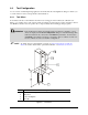
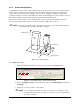
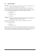
The camera Z-offset is relative to the tooling pin. The tool tip is considered focal distance when the
Z-head is at the upper Z-limit, therefore the Z-offset is always -200.8 mm (-7.916 in.).
NOTE The camera Z-offset is equal to the distance between the focal point and the tooling pin,
not the distance between the lens and the tooling pin.
Z
Y
Coating Surface
X
Focal Distance
Maximum Travel
Figure 4-6 Camera Z-Offset
To configure the camera:
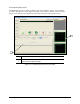
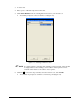
1. Make sure that the Genie Camera is selected as the pointer in ECXP Edit Mode.
Figure 4-7 ECXP Edit Screen - Genie Camera Pointer
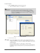
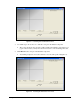
2. Click on Configure > Tools from the pull-down menu, select Genie Camera, and click on
Configure.
3. Follow the on-screen prompts to teach offsets.
NOTE A good teaching location is the corner of a component (i.e. silkscreen on the
board) because it allows the cross-hairs to be centered on a point rather than at
the center of a shape.