Flow Monitoring System Owner's Manual
NOTICE This is an Asymtek publication, which is protected by copyright. Original copyright date 2006. No part of this document may be photocopied, reproduced, or translated to another language without the prior written consent of Asymtek. The information contained in this publication is subject to change without notice. Manuals on the Internet For the convenience of Asymtek customers and field service representatives, copies of this manual can be downloaded from: http://www.asymtek.com/support/manuals.
TABLE OF CONTENTS 1 Introduction ......................................................................................................................................... 1 Overview ............................................................................................................................................... 1 Safety First ............................................................................................................................................ 1 Specifications ............
6 Troubleshooting ................................................................................................................................ 28 Overview ............................................................................................................................................. 28 Safety First .......................................................................................................................................... 28 Record Keeping......................................
1 Introduction Overview Asymtek’s Flow Monitoring System (FMS) aids in closing the dispensing loop of the conformal coating process. The FMS monitors the volume of material dispensed against an established target volume. It is designed for use with the Century® C-740 Series selective conformal coating platforms equipped with either the SC-200 Tri-Mode Swirl Coat ® or SC-205 Film Coater. This manual contains the installation, operations, maintenance, and service instructions for the FMS.
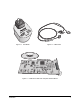
System Description The Flow Monitoring system consists of the following components: • Flow Meter • Computer Interface Board • Cable with three connectors • Easy Coat for Windows NT/XP Flow Meter The Flow Meter is a flow-sensing meter contained in a steel casing (Figure 1-1). The casing has threaded female orifices for connections to the dispensing system fluid line. The top of the flow meter has an electrical connector. The flow meter is mounted on a bracket at the rear of the dispensing system.
Figure 1-1 Flow Meter Figure 1-2 FMS Cable Figure 1-3 FMS Drivers Disk and Computer Interface Board Introduction 3
Tools and Materials The following tools, materials, and documents are needed to install, operate, and maintain the FMS: 4 • Flow Monitoring System Kit, P/N 198007 • Century C-740/C-741 Installation, Operations, and Maintenance Manual • Century C-740 or C-741 Dispensing System with Windows XP or Windows NT 4.0, Service pack 6a or higher • Swirl Coat or SC-205 Film Coater and manuals • Easy Coat User Guide, Version 2.
2 Safety Overview Coating system operation involves heat, air pressure, mechanical and pneumatic devices, electrical power, and the use of hazardous materials. Refer to the Safety section of the C-740/C-741 Installation, Operations and Maintenance Manual prior to installing and operating your Flow Monitoring System. CAUTION! The FMS is a delicate precision instrument. Adhere to listed precautions and use care when installing, operating, or performing maintenance on the FMS.
• Always wear appropriate personal protective equipment (PPE) as recommended by facility safety practices and the material manufacturer’s MSDS. • Make sure that the main power cable and main air supply hose are securely connected before operating the dispensing system. • If in a confined room, ensure adequate and uninterrupted air ventilation, heating, and cooling meet environmental stress limits of personnel and the dispensing system.
3 Installation Overview This section covers the initial installation process for the Flow Monitoring System (FMS) and includes the following topics: " • Installing the Computer Interface Board • Installing the Flow Meter and Cables • Installing the DriverLINX Software • Configuring the DriverLINX software • Configuring the Easy Coat Software NOTE In most cases, the FMS should arrive already installed and configured for your dispensing system from the Asymtek factory.
Installation Installing the Computer Interface Board CAUTION! Use proper Electrostatic Discharge precautions when handling the Computer Interface Board and the CPU units. Failure to do so may cause irreversible damage. 1. Perform a service shutdown as specified in the C-740/C-741 Installation, Operations, and Maintenance Manual. 2. Open the lower cabinet doors to the dispensing system. 3. Disconnect the cables from the computer. ! Label the cables for reinstallation reference. 4.
To install the Flow Meter: " NOTE 1. If continuing from previous section, the system should still be shutdown for service. If not perform a service shutdown as specified in the C-740/C-741 Installation, Operations, and Maintenance Manual. Install the FMS bracket and flow meter as follows: a. Use a hex wrench to install two screws and two washers to secure the bracket to the dispensing system. b. Use a hex wrench to install two screws and two washers to secure the FMS to the FMS bracket. 2.
To connect the cables: 1. Connect the female connector on the FMS Cable to the four-prong male connector on top of the previously installed flow meter. 2. Use a screwdriver to tighten the existing screw on top of the flow meter female connector until the connector gasket is firmly seated.
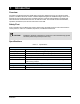
3. Connect the multi-pin male I/O connector of the cable to the Interface Board in the card slot of the computer. 4. Connect the VDC power connector of the cable to the power manager connector labeled Auxiliary DC located in the dispensing system lower cabinet. 5. Close the cabinet doors to the dispensing system, install the power cord to the facility, and power up the dispensing system. 6. You are now ready to install the DriverLINX software.
1 3 2 Item Description 1 Power Manager 2 Auxiliary DC Connector 3 VDC Power Connector Figure 3-4 FMS Cable Installation to Power Manager 12 Installation
Installing the DriverLINX Software 1. Power on the dispensing system as specified in the C-740/C-741 Installation, Operations, and Maintenance Manual. 2. If the ECNT/ECXP software opens, close it. 3. Insert the DriverLINX software CD in the CD-ROM drive. 4. Click the Start button on the Windows Explorer Taskbar and then click on Run. 5. Click on Browse and select D:\Drivers\Keithley\setup.exe to execute the installation procedure. 6. Follow the on-screen prompts and accept the default answers.
4. Use the default Logical Device number (0 – 65535) of 0 and press OK (Figure 3-6). Figure 3-6 Select Logical Device Number 5. From the Configure DriverLINX Device window, go to Model and select KPCI-3102 from the drop-down list, then click OK (Figure 3-7). Figure 3-7 Configuration DriverLINX Device 6. Press the Close button on the DriverLINX Configuration Panel (Figure 3-5). ! 7. The Device Change dialog box opens (Figure 3-8). Select Restart now to complete the software configuration process.
Configuring the Easy Coat Software The first time the Easy Coat software is run you will be prompted to answer a series of questions defining your system configuration. If the Easy Coat software has already been configured, you will need to reconfigure it. Both methods are described below. For detailed information, refer to the Easy Coat User Guide. " NOTE The fluid flow-rate high and low limits are defined during the default settings in the FMS software. Initial Configuration 1.
4 Operation Overview The Flow Monitoring System monitors the volume of material dispensed against an established target volume. The Easy Coat software logs the data and displays the recorded flow volumes on the computer screen in bar graph format. Flow monitoring occurs during production without affecting the cycle rate or increasing material usage. Safety First Operation of the FMS is performed in conjunction with the operation of the dispensing system.
Figure 4-1 Easy Coat Flow Meter Test b. Use the Gun On and Gun Off buttons to start and stop dispensing (Figure 4-2). c. Use the Begin Measurement and End Measurement buttons to start and end a flow reading. When you click the End Measurement button, the flow data is logged into the database. d. Observe the digital readout in the Meter Reading window to verify that the software is incrementing the signal count from the flow meter.
System Startup 1. Ensure the fluid system of the dispensing system is loaded with the selected coating material. " NOTE A light flow of air is permitted to purge solvent from the fluid lines prior to loading the coating material. Air pressure to the fluid reservoir should be less than 5 psi for purging air through the fluid system. Too much airflow causes a humming or whining sound from the flow meter gears. To alleviate this, decrease the air pressure. 2.
" NOTE Begin Flow Measurement and End Flow Measurement instructions are only available if the flow meter option is installed in the fluid system and configured in Easy Coat. The instruction buttons appear on the Conformal Coating tab. Monitoring System Operation • Be alert for the automatic alarm when flow irregularity is detected by the Easy Coat software. • If you hear a continuous beep or see the red light flash from the Light Beacon, production has been halted.
5 Maintenance and Service Overview This section contains recommended maintenance and service procedures. For optimum performance of your Flow Monitoring System, perform recommended procedures at the suggested intervals. Safety First Please familiarize yourself with the Safety sections of this manual and the Century Series C-740/C-741 Installation, Operations, and Maintenance Manual before performing maintenance or service on the FMS.
Service The flow meter can be disassembled for cleaning and service. See Section 7 - Parts Replacement for a list of replacement parts. Tools and Materials Needed: • Screwdriver • Non-metallic Pin • Hex Wrench • Nozzle Bristle Brush • Torque Wrench • Solvent • Plastic Tweezers • Shop Cloth Removing the Flow Meter CAUTION! The flow meter is a delicate precision instrument. Handle with care to maintain its integrity and functionality. 1.
4. Disconnect the fluid lines and remove the elbow fittings (Figure 5-2). CAUTION! Avoid accidental spills of solvent or coating material during removal that could damage the dispensing system. 5. Use a hex wrench to remove the two screws that secure the flow meter to the bracket and remove the flow meter from the bracket. 6. Drain residual fluids from the flow meter threaded holes from each side.
Disassembling the Flow Meter 1. Use a 5 mm hex wrench to remove eight socket head screws from the flow meter (Figure 5-3). 2. Hold the flow meter so that the electrical connector is facing upwards, then remove the tophalf casing by carefully lifting it up from the bottom-half casing. 3. To facilitate removal of the delicate shims and the gears, soak the bottom-half casing in solvent to dissolve any cured coating material.
4. Using fingers, slightly rotate the gears, then turn the bottom-half casing upside down on a shop-rag and carefully shake the two gears and four shims and let them fall on the shop cloth. CAUTION! Do not use a screwdriver or metal tweezers to pry out shims and gears. This can damage the unit and result in inaccurate readings. Do not expose the electrical connector to solvent. 5. Inspect the shims and gears for wear or damage. 6.
Cleaning the Flow Meter 1. Soak the shims, gears, and bottom-half casing in solvent and clean with a nozzle bristle brush. CAUTION! Do not expose the electrical connector to solvents as this can damage the gasket and connector and cause electrical problems. 2. Carefully clean the top-half casing, making sure the electrical connector is not exposed to any solvent. 3. Inspect the cleaned parts for cleanliness and repeat the above cleaning steps if needed. Reassembling the Flow Meter 1.
Replacing the Flow Meter If cleaning and replacing interior parts does not restore the flow meter to its original performance, it must be replaced. Proceed as follows: 1. Obtain a new flow meter. Refer to Section 7 - Parts Replacement. 2. Remove the old flow meter as described in “Removing the Flow Meter” in this section. 3. Refer to the installation instructions in Section 3 - Installation to install the new flow meter. Replacing the FMS Cable 1. Remove the faulty FMS cable as follows: a.
Bracket Replacement 1. Remove the bracket as follows (Figure 5-4): a. Using a hex wrench, carefully remove the two screws and two washers 1 that secure the flow meter to the bracket. b. Carefully set aside the flow meter without causing strain on the fluid lines. c. 2. Using a hex wrench, remove the two screws and two washers 2 that secure the bracket to the dispensing system. Install a new replacement bracket by following the instructions in Section 3 - Installation.
6 Troubleshooting Overview If you have difficulty operating your Flow Monitoring System, use this section to identify a possible solution to the problem. If you have difficulties not listed in this section, or the suggested solution does not correct the problem, contact Asymtek Technical Support.
Table 6-1 Flow Monitoring System Troubleshooting Symptom The software is not recording the flow of coating material. The recorded flow is varying greatly. Beacon red light is flashing, continuous beeping sound. The flow meter gears produce a humming or whining sound. The software is counting signals when there is no obvious flow of coating material. Troubleshooting Probable Cause Corrective Action Electrical connections are loose or FMS cable is faulty.
7 Parts Replacement Overview This section includes general information for ordering recommended spares and replacement parts for the Flow Monitoring System (FMS). Safety First Please familiarize yourself with the Safety sections of this manual and the Century Series C-740/C-741 Operations, Installation and Maintenance Manual before replacing any parts. CAUTION! Parts replacement should be performed by trained personnel only.
Credit and Exchanges Contact Asymtek Customer Service for credit or exchanges of recommended spare parts or refurbished components (components restored to original specifications but not sold as new). Return Material Authorization Contact Asymtek Technical Support to obtain a Return Material Authorization (RMA) before returning any parts. " NOTE Find your local Technical Support and Customer Service contacts on the Asymtek web site, www.asymtek.com. Click on Tech Support or Contact Us.
Asymtek Headquarters 2762 Loker Avenue West Carlsbad, CA 92010-6603 USA Tel: (760) 431-1919 1-800-ASYMTEK (1-800-279-6835) P/N 7211898, Rev A © 2006