
User Manual

Power-up and Testing 4-1
4 Power-up and Testing
4.1 Overview
This section describes the power-up and testing procedures for making sure that all system components
are functioning and communicating properly. This section covers the following topics:
Pneumatic Connections
Testing the System
Electrical Connections
Robot/Conveyor I/O
Exhaust Connection
Pneumatics
Connecting Power and Air Supply Robot (Dispensing Head) Function
Powering On the System Conveyor Function
Camera States Coating System Options
Starting Easy Coat for Windows (ECXP)
4.2 Safety First
Operation of your SL-940E/SL-941E Series Conformal Coating System involves heat, air pressure,
electrical power, mechanical devices, and the use of hazardous materials. It is essential that every person
servicing or operating the coating system fully understands all hazards, risks, and safety precautions.
Refer to Section 2 - Safety for additional information.
WARNING! CAUTION!
To ensure optimal performance and safety, it is necessary to install the coating
system in a facility that meets the necessary requirements listed in Section 10 -
Specifications. If you have any questions, please contact Nordson ASYMTEK
Technical Support.
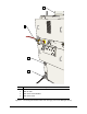
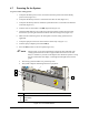
4.3 Pneumatic Connections
Depending on system configuration, the SL-940E/SL-941E requires 586 to 620 kPa (85 to 90 psi) up to
0.34 m
3
/min (12 SCFM) max. of clean, dry air delivered through a 12.7 mm (0.5 inch) pipe or hose.
Connect the air supply to the ¼ -inch NPT quick-disconnect fitting at the Main Air Inlet (Figure 4-1).
NOTE The maximum air supply pressure should not exceed 620 kPa (90 psi). The system is
equipped with a 100 psi relief valve.
WARNING! CAUTION!
All system pneumatic connections should be checked before the main air
is connected.
Refer to Appendix B for SL-940E/SL-941E pneumatic diagrams.