Single Package Heat Pump Installation Instructions 460 Volt Q4 Series IMPORTANT Read these instructions thoroughly before starting the installation. Follow all precautions and warnings contained within these instructions and on the unit. These instructions are primarily intended to assist qualified individuals experienced in the proper installation of heating and/or air conditioning appliances. Some local codes require licensed installation/service personnel for this type equipment.
TABLE OF CONTENTS OWNER INFORMATION .......................................................................................................... 3 SPECIFICATIONS ..................................................................................................................... 4 SAFETY CONSIDERATIONS ................................................................................................... 5 • Labels, Tags. ............................................................................................
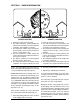
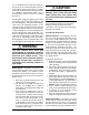
SECTION 1. OWNER INFORMATION 5 2 5 1 3 4 6 1 3 4 6 2 WINTER HEATING SUMMER COOLING 1. Outdoor air enters the heat pump. 2. The cold, heat-transfer section (outdoor coil) extracts the heat from the air as the refrigerant evaporates from a liquid to a cold gas. 3. The refrigerant, compressed to a hot gas by the heat pump, carries the heat to the heattransfer section (indoor coil). 4. The hot, heat-transfer section (indoor coil) releases the heat as the refrigerant condenses from a gas to a liquid.
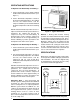
OPERATING INSTRUCTIONS To Operate Your Heat Pump For Cooling — FAN SWITCH 1. Set the thermostat system switch to COOL and the thermostat fan switch to AUTO. (See Figure 1) 2. Set the thermostat temperature selector to the desired cooling temperature. The outdoor unit fan, the indoor blower, and the compressor will all cycle on and off to maintain the indoor temperature at the desired cooling level.
All models are shipped from the factory with the following: 1. 2. 3. 4. Zero clearance to combustibles Multi-speed direct-drive blower. Blower Speed Relay. Horizontal or Down flow duct connections. The unit dimensions are shown in Figure 3. Optional field-installed electric heater kits are available in 9 kw and 15 kw heating capacities. A separate installation instruction document for the electric heaters and their application accompanies this one.
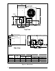
24.9 3/4" NPT Female Drain Connector SUPPLY 47.5 CG 13.5 16.0 16.0 13.5 B 13.3 12.0 12.0 23.5 RETURN A Top View 1.8 1.75 Ø Power Entry (Capped) 1.25 Ø Power Entry 0.88 Ø Control Wiring Entry 28.7 SUPPLY C 26.0 16.0 13.5 22.4 13.5 11.2 11.2 10.0 Side View Model No. Unit Weight Q4SA-036 Q4SA-048 Q4SA-060 340 345 400 24.9 55.8 Back View Center of Gravity A 28.0 28.0 29.5 B 26.0 26.0 26.5 Height (in inches) C with base rails without base rails 33.7 31.3 33.7 31.3 37.7 35.
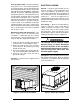
2" 36" 36" 36" 6" Figure 4. Minimum Clearances UNIT INSTALLATION Ground Level — When installing the unit at ground level, provide a concrete mounting pad separate from the building foundation. The pad must be level to insure proper condensate disposal and strong enough to support the unit’s weight. Refer to Figure 3. Make sure the slab is a minimum of 2" above the grade and in an area that drains well (See Figure 6). Rigging and Hoisting — The unit should be lifted using slings and spreader bars.
Acoustical Duct Work — Certain installations may require the use of acoustical lining inside the supply duct work. Acoustical insulation must be in accordance with the current revision of the Sheet Metal and Air Conditioning Contractors National Association (SMACNA) application standard for duct liners. Duct lining must be UL classified batts or blankets with a fire hazard classification of FHC-25/50 or less.
Use a separate branch electrical circuit for this unit. A means of electrical disconnect must be located within sight of and readily accessibility to the unit. Internally mounted circuit breakers are available as field installed options. These circuit breakers can be used as an electrical disconnect. Provide power supply (or supplies) for the unit in accordance with the unit wiring diagram, and the unit rating plate.
interval settings are available: 30 minutes, 60 minutes, and 90 minutes. Time setting selection is dependent on the climate where the unit is being installed. • Example 1. Dry climate of Southern Arizona. A 90 minute setting is recommended. • Example 2. Moist climate of Seattle, Washington. A 30 minute setting is recommended. To set the cycle timer, place the timing pin on the defrost control board to the desired time interval post.
UNIT MAINTENANCE ! CAUTION: ! WARNING: To avoid risk of electrical shock, personal injury, or death, disconnect all electrical power to the unit before performing any maintenance or service. The unit may have more than one electrical supply. Refrigerant Charging — The Q4 packaged heat pumps are fully charged at the factory . The system refrigerant charge can be checked and adjusted through the service ports provided in the front panel.
X W3 ECONOMIZER PLUG 1 2 3 4 Blue 5 6 7 8 9 (Optional,Check Thermostat Instructions) FROM BLOWER RELAY W2 X W3 Green W2 ECONOMIZER PLUG Y2 Y1 1 2 3 4 Blue 5 6 7 8 9 C R Y G O O W2 E R (Optional,Check Thermostat Instructions) FROM BLOWER RELAY Green Y2 Y1 C R Y G O O W2 E R E INDOOR THERMOSTAT SUB-BASE DEFROST BOARD Typical Wiring (Field Supplied) for 1-Stage Cool, 1-Stage Heat INDOOR THERMOSTAT SUB-BASE E DEFROST BOARD Typical Wiring (Field Supplied) for 2-Stage Cool, 1-Stage Heat F
OUTDOOR TEMPERATURE (° F) 0 10 20 30 40 50 60 Suc. Disch. Disch. Suc. Disch. Disch. Suc. Disch. Disch. Suc. Disch. Disch. Suc. Disch. Disch. Suc. Disch. Disch. Suc. Disch. Disch. Press. Press. Temp. Press. Press. Temp. Press. Press. Temp. Press. Press. Temp. Press. Press. Temp. Press. Press. Temp. Press. Press. Temp. Table 2.
OUTDOOR TEMPERATURE (° F) 0 10 20 30 40 50 60 Suc. Disch. Disch. Suc. Disch. Disch. Suc. Disch. Disch. Suc. Disch. Disch. Suc. Disch. Disch. Suc. Disch. Disch. Suc. Disch. Disch. Press. Press. Temp. Press. Press. Temp. Press. Press. Temp. Press. Press. Temp. Press. Press. Temp. Press. Press. Temp. Press. Press. Temp. Table 2a.
Table 3. Q4SA Cooling Charging Charts Suct. Pres. 72 74 76 78 80 82 84 86 88 90 92 OUTDOOR TEMPERATURE ( °F ) 70 75 80 85 90 95 100 105 Disch. Disch. Disch. Disch. Disch. Disch. Disch. Disch. Disch. Disch. Disch. Disch. Disch. Disch. Disch. Disch. Pres. Temp. Pres. Temp. Pres. Temp. Pres. Temp. Pres. Temp. Pres. Temp. Pres. Temp. Pres. Temp.
Table 3a. Q4SA Cooling Charging Charts Suct. Pres. 68 70 72 74 76 78 80 82 84 86 88 OUTDOOR TEMPERATURE ( °F ) 70 75 80 85 90 95 100 105 Disch. Disch. Disch. Disch. Disch. Disch. Disch. Disch. Disch. Disch. Disch. Disch. Disch. Disch. Disch. Disch. Pres. Temp. Pres. Temp. Pres. Temp. Pres. Temp. Pres. Temp. Pres. Temp. Pres. Temp. Pres. Temp.
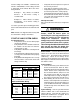
Q4 ACCESSORIES Description Roof Curb (8") Roof Curb (14") Manual Fresh Air Damper Economizer, downflow Supply/return transition, 16" Supply/return transition, 18" Concentric diffuser, flush, 16" Concentric diffuser, flush, 18" Concentric diffuser, step down 16" Concentric diffuser, step down 18" Motorized Fresh Air Damper Economizer, horizontal (special order) Power Exhaust, downflow economizer (special order) Power Exhaust horizontal economizer (special order) Hail guard 30x76 (special order, see Note 1) H
Convertible Packaged Heat Pump 460 Volt NNOTES: 1. Disconnect all power before servicing. 2. For supply connections use copper conductors only. 3. If any of the original wire as supplied with the furnace must be replaced, it must be replaced with wiring material having a temperature rating of at least 105°C. 4. For supply wire ampacities and overcurrent protection, see unit rating plate. Three Phase 1. 2. Couper le courant avant de faire letretien. Employez uniquement des conducteurs en cuivre.
INSTALLER: PLEASE LEAVE THESE INSTALLATION INSTRUCTIONS WITH THE HOMEOWNER. AIR G -C AS C O DI DI TI IN N LY I A I R - CON N I NG G W I TH TIO ® G AI A R R N N TH I S U N I T H A O MP S RT I F I E D CE O BE EN R- CO N D ITI O NI N I S 21 TA ND A R D 0 R ¢707885W¤ St. Louis, MO 707885A 707885A (Replaces 7078850) Specifications and illustrations subject to change without notice and without incurring obligations.