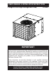
USER’s MANUAL & INSTALLATION INSTRUCTIONS 2 Stage R-410A Single Package Heat Pump 15 SEER IMPORTANT Please read this information thoroughly and become familiar with the capabilities and use of your appliance before attempting to operate or maintain this unit. Keep this literature where you have easy access to it in the future. If a problem occurs, check the instructions and follow recommendations given.
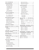
SAFETY INFORMATION ...............................3 USER INFORMATION ...................................3 About the Heat pump ................................ 3 Operating Instructions ............................... 3 Cooling Operation ................................... 3 Heating Operation ................................... 3 Emergency Heat ..................................... 3 Defrost ....................................................3 System Shutdown ...................................
SAFETY INFORMATION IMPORTANT: Please read all instructions before servicing this equipment. Pay attention to all safety warnings and any other special notes highlighted in the manual. Safety markings are used frequently throughout this manual to designate a degree or level of seriousness and should not be ignored. WARNING indicates a potentially hazardous situation that if not avoided, could result in personal injury or death.
At the beginning of the defrost cycle, both the outdoor condenser fan and compressor will turn off. After approximately 30 seconds, the compressor will turn on and begin to heat the outdoor coil causing the ice and snow to melt. NOTE: While the ice and snow is melting, some steam may rise from the outdoor unit as the warm coil causes the melting frost to evaporate. When defrost is completed, the outdoor fan motor will start, and the compressor will turn off again.
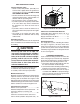
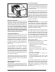
HEAT PUMP INSTALLATION Locating the Heat pump • Select a solid, level position, preferably on a concrete slab, slightly above the grade level, and parallel to the home. DO NOT PLACE UNIT UNDER THE HOME. • The hot condenser air must be discharged up and away from the home, and if possible, in a direction with the prevailing wind. • Do not place the unit in a confined space.
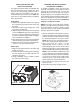
INSTALLING RETURN AND SUPPLY AIR FITTINGS The supply and return fittings are included with the unit and located in the supply duct. They attach to the unit openings (Figure 4) with a flange and bead arrangement and may be, secured with two sheet metal screws. Note: For easier access, install fittings before positioning unit in final location. Supply Duct 1. Position the supply duct collar so the edge of the unit opening fits between the flange and the bead. 2.
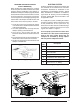
LOCATING AND INSTALLING THE SUPPLY DAMPER(S) When locating the supply damper(s), carefully check floor joists and frame members that could interfere with the installation of the damper or flexible duct. Ideally, the damper (Figure 6) should be located in the bottom of the main duct, forward of center of the home, at least three feet from the nearest register.The round supply opening in the slanted side of the damper should face the side of the home where the heat pump is located.
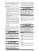
Note: For highly resistive duct systems it may be necessary to add an additional return air duct and or supply to achieve maximum performance and prevent coil icing and refrigerant flood back. Connecting the Return and Supply Air Flexible Ducts • The return duct for all units is 14” diameter. • The supply duct for all units is 12” diameter. • The flexible ducts can be connected to the corresponding fittings with the clamps provided with the ducts.
Low Pressure Switch The low pressure switch is factory installed and located in the suction line internal to the unit. The switch is designed to protect the compressor if a loss of charge occurs. Under normal conditions, the switch is closed. High Voltage Low Voltage Figure 8. Power Entry Overcurrent Protection Generally, the best fuse or breaker for any heat pump is the smallest size that will permit the equipment to run under normal usage and provide maximum equipment protection.
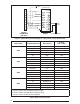
Green (from Blower Relay) out Y2 R Y out Y W2 R O Y1 C Y2 G out in C Y2 E DF L L DF2 INDOOR THERMOSTAT SUB-BASE DEFROST BOARD 1 Brown 2 Orange 3 4 5 6 7 8 9 Accessory Heat Plug Figure 9. Typical Wiring (Field Supplied) for 2-Stage Cool, 2 Stage Electric Heat Model Q5RF X24K X36K X48K X60K Wire Color/Speed Tap Motor Speed Air Flow (@ 0.
Control is uncalibrated when power is applied. Calibration occurs after a defrost cycle. The control initiates defrost after 34 minutes of accumulated compressor run time in heating with coil temperature below 35° F. The defrost cycle terminates when the coil sensor reaches termination temperature or after 14 minutes. Note: All units are shipped from the factory with the default termination temperature set at 70° F. 6. Install one spacer next between the plastic clip and mounting bracket. 7.
SYSTEM OPERATION Pre-Start Checklist The following check list should be observed prior to starting the unit. Is the unit level? Unit should be level or slightly slanted toward the drain for proper condensate drainage. Is the unit installed with the proper clearances as listed in Figure 2 (page 5)? Is the wiring correct according to the wiring diagram and electrical codes? Are all the wiring connections tight? Check the condenser fan to make sure it turns freely.
Anti Short Cycle Timer Test The 3 minute time delay feature can be bypassed by shorting the “TEST” pins together. Heating Mode When the “TEST” pins are shorted together for more than 1 second, the control will switch between defrost mode and heating mode as described in the Defrost Test Procedure section (page 12). Cooling Mode When the ‘TEST” pins are shorted together for more than 1 second, the Anti Short Cycle Timer will be bypassed.
Refrigerant Charging Charts for Cooling Mode of Operation Q5RF-X24K CHARGING CHART 600 575 550 525 500 R em ove refrigerant w hen above c urve LIQUID PRESSURE (PSIG) 475 450 425 400 375 350 325 Add refrigerant w hen below c urve 300 275 250 225 200 70 75 80 85 90 95 100 105 110 115 120 125 130 135 140 135 140 LIQUID TEMPERATURE (F) Figure 11.
Refrigerant Charging Charts for Cooling Mode of Operation - Continued Q5RF-X48K CHARGING CHART 600 575 550 525 500 R em ove refrigerant w hen above c urve LIQUID PRESSURE (PSIG) 475 450 425 400 375 350 325 Add refrigerant w hen below c urve 300 275 250 225 200 70 75 80 85 90 95 100 105 110 115 120 125 130 135 140 135 140 LIQUID TEMPERATURE (F) Figure 13.
10 Disch. Suc. Liquid Temp. Press. Press. 126 52 226 124 53 232 122 238 54 120 55 244 56 118 249 116 57 255 114 58 261 10 Disch. Suc. Liquid Temp. Press. Press. 102 50 224 100 51 230 98 236 52 96 53 242 54 94 248 92 55 254 90 56 260 0 Suc. Liquid Press Press. 37 205 38 212 219 39 40 226 41 233 42 240 43 247 0 Suc. Liquid Press Press. 37 188 38 195 202 39 40 209 41 216 42 223 43 230 20 Disch. Suc. Liquid Temp. Press. Press.
10 Disch. Suc. Liquid Temp. Press. Press. 160 45 268 158 46 273 156 279 47 154 48 285 49 152 291 150 50 297 148 51 303 10 Disch. Suc. Liquid Temp. Press. Press. 104 46 229 102 47 235 100 241 48 98 49 247 50 96 253 94 51 258 92 52 264 0 Suc. Liquid Press Press. 29 263 30 270 277 31 32 284 33 291 34 298 35 305 0 Suc. Liquid Press Press. 31 205 32 212 219 33 34 226 35 233 36 240 37 247 20 Disch. Suc. Liquid Temp. Press. Press.
Figure 15. Q5RF/PPH2RF Series Wiring Diagram - 2 & 3 Ton Units 240V 24V COM LEGEND: RED FIELD WIRING LOW VOLTAGE HIGH VOLTAGE 3 AMP FUSE TRASFORMER RED AMBIENT THERMISTOR COIL THERMISTOR L COILG COIL AMBG AMBIENT WHITE TO T-STAT BLACK BLACK R DF1 DF2 C OUTDOOR MOTOR BLACK C Y2 Y R W2 W2 O IN OUT S BLUE ORANGE REV VALVE HPS LPS Y OUT Y2 OUT BLACK DEMAND DEFROST CONTROL BOARD RED TO “G” ON T-STAT BLACK HIGH SPEED BLOWER RELAY (24V) BLUE BLUE BLUE YELLOW NOTES: 1.
Figure 16.
INSTALLER PLEASE LEAVE THESE INSTALLATION INSTRUCTIONS WITH THE HOMEOWNER. ¢709064-¤ O’Fallon, MO 709064B 709064B (Replaces 709064A) Specifications and illustrations subject to change without notice or incurring obligations. Printed in U.S.A.