Installation Manual NORITZ AMERICA CORPORATION TANKLESS GAS WATER HEATER NR98DVC (GQ-2857WX-FFA US) (Indoor Installation) Potential dangers from accidents during installation and use are divided into the following three categories. Closely observe these warnings, they are critical to your safety. DANGER WARNING CAUTION DANGER indicates an imminently hazardous situation which, if not avoided, will result in death or serious injury.
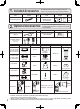
1. Included Accessories Part Shape Q’ty Part 5 Owner's Guide, Warranty, Installation Manual (this document) Anchoring Screw 2. Optional Accessories Part Shape Q’ty Quick Connect Cord (QC-2) 1 Isolation Valves * Description 4"-CVP-4STR 12"-CVP-12STR 24"-CVP-24STR 36"-CVP-36STR 11"-CVP-11ADJ 16"-CVP-16ADJ 40"-CVP-40ADJ Shape Q’ty 1 each The accessories listed below are not included with the units, but may be necessary for installation.
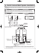
. Quick Connect Multi System Installation • The Quick Connect Multi System allows the installation of two units together utilizing only the Quick Connect Cord. The Quick Connect Cord is 6' (2m) long. Install the units 2-18" (50-457mm) apart from each other to ensure the cord will be able to reach between the units. (See Typical Plumbing diagram).
. Before Installation DANGER Checkup • Check the fixing brackets and vent pipe yearly for damage or wear. Replace if necessary. WARNING Precautions on Vent Pipe • This appliance requires the use of special concentric type vent pipe specified by Noritz America. Do not attempt to use materials that are not specified for use on this appliance. Improper venting may result in a fire, property damage, or exposure to Carbon Monoxide.
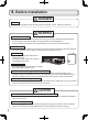
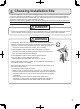
. Choosing Installation Site * Locate the appliance in an area where leakage from the unit or connections will not result in damage to the area adjacent to the appliance or to the lower floors of the structure. When such installation locations cannot be avoided, a suitable drain pan, adequately drained, must be installed under the appliance. The pan must not restrict combustion air flow. * As with any water heating appliance, the potential for leakage at some time in the life of the product does exist.
CAUTION • The water heater is designed for indoor installation only. Never install it outdoors or in a bathroom, it may be damaged or a fire may be caused. • Consult with the customer concerning the location of installation. • Install the water heater in an area that allows for the proper clearances to combustible and noncombustible construction. Consult the rating plate on the appliance for proper clearances.
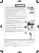
6. Installation Clearances WARNING Before installing, check for the following: Install in accordance with relevant building and mechanical codes, as well as any local, state or national regulations, or in the absence of local and state codes, to the National Fuel Gas Code ANSI Z223.1/NFPA 54 – latest edition. In Canada, see the Natural Gas and Propane Installation Code CSA B149.1 - latest edition for detailed requirements.
Clearance Requirements from Vent Terminations to Building Openings * All clearance requirements are in accordance with ANSI Z21.10.3 and the National Fuel Gas Code, ANSI Z223.1 and in Canada, in accordance with the Natural Gas and Propane Installation Code CSA B149.1.
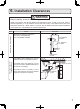
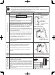
Be sure to do Item • The weight of the device will be applied to the wall. If the strength of the wall is not sufficient, reinforcement must be done to prevent the transfer of vibration. • Do not drop or apply unnecessary force to the device when installing. Internal parts may be damaged and may become highly dangerous. • Install the unit on a vertical wall and ensure that it is level. Check Illustration CAUTION mounting bracket (upper) mark (0.
8. Vent Pipe Installation WARNING Be sure to do CARBON MONOXIDE POISONING Follow all vent system requirements in accordance with relevant local or state regulation, or, in the absence of local or state code, in the U.S. to the National Fuel Gas Code ANSI Z233.1/NFPA 54 – latest edition, and in Canada, in accordance with the Natural Gas and Propane Installation Code CSA B149.1 – latest edition. • This appliance requires the use of special concentric type vent pipe specified by Noritz America.
Maximum Vent Length Adjustment Dip Switches The unit can be adjusted to accommodate longer vent runs; refer to the below table to find the maximum vent length based on the number of elbows. Adjust the dip switches according to the vent condition noted in the tables below. Note: By default, the unit has been set to the " 1 minimum length" condition. When adjusting the dip switches for longer vent runs, the BTUH input of the appliance will be reduced by up to 8%.
• Exceeding the maximum vent length is dangerous and may result in bad combustion. • Install the vent terminal so that all exhaust is directed to and all intake air is taken from outdoors. • Do not store hazardous or flammable substances near the vent terminal. • Slope the vent pipe 1/4" (6mm) for every 12" (300mm) either towards the horizontal termination or towards the integrated condensate collector.
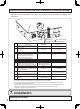
Vertical Vent Termination 5' (1.5m) or more Rain Cap Air Intake Pipe Roof Flashing (Base and Adapter) Firestop/ Support Hanger Straps Firestop Elbow Slope vent Upwards Elbow WARNING Prohibited to install 90 degree adjustable elbow (CVP-90ADJELB) in this portion. Install 90 degree elbow (CVP-90ELB) only. Drain condensate according to local codes. Condensate collector must be used if the total vent run exceeds 3' (0.9m). • Terminate at least 6' (1.
9. Gas Piping Follow the instructions from the gas supplier. CAUTION The guidelines and examples we have provided in this manual section are for reference only. The sizing and installation of the gas system for this water heater, as with any gas appliance, is the sole responsibility of the installer. The installer must be professionally trained to do such work and must always follow all local and national codes and regulations. Gas line sizing calculations must be performed for every installation.
WARNING Pressure Test The appliance and its gas connections must be leak tested before placing the appliance in operation. The appliance must be isolated from the gas supply piping system by closing its individual manual shutoff valve during any pressure testing of the gas supply piping system at test pressures equal to or less than ½ psig (3.5 kPa). We do not recommend pressure testing in excess of ½ psig (3.5kPa).
Table 1. For Less than 8” WC initial supply pressure Maximum Natural Gas Delivery Capacity (0.
Table 3. Maximum Undiluted Propane (LP) Delivery Capacity in Thousands of BtuH (0.
10. Water Piping Installation and service must be performed by a qualified plumber. In the Commonwealth of Massachusetts, this product must be installed by a licensed plumber or gas fitter in accordance with the Massachusetts Plumbing and Fuel Gas Code 248 CMR Sections 2.00 and 5.00. Observe all applicable codes. This appliance is suitable for combination potable water and space heating applications. It cannot be used for space heating applications only.
Supply water piping • Do not use PVC, iron, or any piping which has been treated with chromates, boiler seal or other chemicals. • Mount a check valve and a shut off valve (near the inlet). • In order for the client to use the water heater comfortably, 98.1 to 491 kPa (14 to 70 PSI) of pressure is needed from the water supply. Be sure to check the water pressure. If the water pressure is low, the water heater cannot perform to its full capability, and may become a source of trouble for the client.
Water Treatment If this water heater will be installed in an application where the supply water is hard, the water must be treated with either the Noritz H2Flow or ScaleShield or a water softener. Refer to the below tables for suggested treatment and maintenance measures to be taken based on the water hardness level. If this water heater will be installed in an application where the supply water is hard, Scale Build-up may cause damage to the Heat Exchanger.
Procedure for Flushing the Heat Exchanger This procedure is only intended for use by a qualified service professional or authorized Noritz Service Representative. Any unauthorized use of this procedure may result in voiding the warranty.Please contact Noritz America (866-766-7489) for additional support. ** , it means If the error code “C #*~C #*” is flashing on the Remote C there is Scale Build-up in the Heat Exchanger.The Heat Exchanger needs to be flushed*** to remove the Scale Build-up.
䍾㻼㼞㼛㼏㼑㼐㼡㼞㼑㻌䠎㻚㻌Flushing the Heat Exchanger (For Single Unit) 䍿 1. Open the Front Cover. 2. Connect the “blue connector*****” for flushing” near the Circuit Board. Water Heater Circuit Board Connect ***** The connector color is blue and labeled “FLUSH”. Manifold Plate FLUSH CCC 3. Then the code “CCC” is displayed on the 㻾㼑㼙㼛㼠㼑㻌㻯㼛㼚㼠㼞㼛㼘㼘㼑㼞㻚 4. Turn on the circulating pump to circulate the flushing solution through the water heater for 1 hour at a rate of 1.5 gallons per minute or more. 5.
㻵㼚㻌㼏㼍㼟㼑㻌㼛㼒㻌㼠㼔㼑㻌䇾㻽㼡㼕㼏㼗㻌㻯㼛㼚㼚㼑㼏㼠㻌㻹㼡㼘㼠㼕㻌㻿㼥㼟㼠㼑㼙㻌㻼㼞㼛㼏㼑㼐㼡㼞㼑䇿 1. Connect the “blue connector for flushing” of need to be flushed. (The water heater is isolated from Quick Connect Multi system when the “blue connector for flushing” is connected. Not need to disconnect the 㻽㼡㼕㼏㼗 Connect Cord.) Sub Water Heater Main Water Heater Connect Circuit Board Manifold Plate FLUSH Quick Connect Cord Remote Controller Do not need to disconnect. 2.
11. Plumbing Applications Recirculation System Tankless Gas Water Heater Hot Water Return Cold Water Supply Fixtures Expansion Tank (Install according to local code) Isolation Kit(*4) Gas Supply 3. Set the Aquastat to 10˚F below the set output temperature. An aquastat is the minimum pump control requirement in order to maintain the full recirculation waranty. If it is not installed, the water heater can not detect the Scale Build-up in the Heat Exchanger. 4.
12. Electrical Wiring Consult a qualified electrician for the electrical work. Do not connect electrical power to the unit until all electrical wiring has been completed. Disconnect Power This appliance must be electrically grounded in accordance with local codes, or in the absence of local codes, with the National Electrical Code, ANSI/NFPA 70. In Canada, the latest CSA C22.1 Electrical Code. Caution: Label all wires prior to disconnection when servicing controls.
Operation Panel * Only one operation panel can be connected to the water heater. A malfunction may occur if two or more operation panels are connected. * The water heater has been factory set to allow a maximum temperature setting of [120 °F / 50 °C]. To access higher temperature settings through the remote controller, follow the below steps. 1. Turn the water heater off by pressing the Power On/Off Button on the operation panel. 2.
Changing Other Features Adjusting the Temperature Display Note: The setting must be done within the first 10 minutes of connecting electrical power to the water heater. Table of Setting Items Item No. Item 12 Celsius/Fahrenheit display mode. Operation panel Display Choices (factory defaults shaded) °F (Fahrenheit) °C (Celsius) Setting Button Power On/Off Button Flow Meter Alarm Set button Setting Procedure 1. Turn the water heater off by pressing the Power On/Off Button on the operation panel. 2.
Pump Wiring * This feature is not available when using the Quick Connect Multi System feature. Connecting the pump control wire PUMP 1. Leave enough slack so that the pump control wires will stay connected if the unit is removed from the wall. 2. Remove the front cover of the heater (4 screws). 3. Cut off the connector at the end of the pump control wires. 4.
Connecting Quick Connect Cord-2 For Quick Connect Multi System Installation use part #QC-2 only. (sold separately). Caution The wire coloring on the Quick Connect Cord-2 will not be the same as the wire coloring of the connection plug inside the unit. * The operation panel can be connected to either unit A or B. Do not connect a operation panel to both units. * Disconnect the operation panel from either unit A or B prior to installing the Quick Connect Cord. Quick Connect Cord-2 1.Red 2.Black 3.White 4.
13. Maintenance Periodically check the following to ensure proper operation of the water heater. • The venting system must be examined periodically by a qualified service technician to check for any leaks or corrosion. • The burner flame must be checked periodically for a proper blue color and consistency. • If the flame does not appear normal, the burner may need to be cleaned. • If the burner needs to be cleaned, it must be performed by a qualified service technician.
CAUTION Handling after trial operation • If the unit will not be used immediately, close off all gas and water shutoff valves, drain all of the water out of the unit and the plumbing system to prevent the unit and system from freezing, and bleed the gas out of the gas line. Freezing is not covered by the warranty. WARNING A fire or explosion may result if these instructions are not followed, which may cause lose of life, personal injury or property damage.
15. Dimensions 13.2" (336mm) 0.4" - 1.8" (10 - 45mm) 11.0" (280mm) 4.4" (113mm) 4.8" (120mm) 1.0" (26mm) 6 - 0.2" x 0.4" (6 x10mm) OBLONG HOLE 5.5" (140mm) 3.9" (100mm) 2.8"(70mm) 1.4" (36mm) 1.1" (28mm) Ø5.0" (Ø128mm) Ø3.1" (Ø80mm) 13.8" (350mm) 13.1" (334mm) FLUE COLLAR AIR INLET CONDENSATE DRAIN 2.0" (50mm) 3.3" (85mm) 4.7" (120mm) 23.6" (600mm) 24.6" (626mm) 22.3" (567mm) 2 - Ø0.5" (Ø 13mm) 0.4" - 1.8" (10 - 45mm) WIRING THROUGHEAY (AC120V) GAS INLET 2 - 0.3" x 0.5" (6.
Optional Remote Controller RC-9018M Requests to Installers ● In order to use the water heater safely, read this installation guide carefully, and follow the installation instructions. ● Failures and damage caused by erroneous work or work not as instructed in this manual are not covered by the warranty. ● Refer to the Installation Manual provided with the water heater for complete installation details.
Included Parts List Remote Controller (1) (The value in ( ) indicates the quantity.) Mounting bracket (1) Raised countersunk head wood screw Wall anchor (2) Raised countersunk head screw (2) (2) Machine screw (2) (For junction box installation) Notes on the Installation Location Connection of Remote Controller Cord • The remote should be installed in an easily accessible location.
2. Remove the decorative frame from the remote controller. (The remote controller is inserted in the decorative frame.) Main remote controller body Remove the remote controller while pulling the decorative frame forward. Decorative frame 3. Connect the remote controller wires to the cord supplied with the water heater. * Do not remove the remote controller wires from the terminal block, connect these wires to the remote controller cord. * Do not remove the insulating cover (clear).
Connecting of Remote Controller Cord to Water Heater. 1. Remove the front cover of the heater (4 screws). 2. Disconnect the operation panel connector from other unit. Operation panel connector 3. Cut off the connector at the end of the operation panel wires ant the Y-shaped terminals (two-cord) of remote controller cord. 4. Wire the remote controller cord through the wiring throughway and connect them to the wiring inside the heater .
Optional Remote Controller • Applicable Model Remote controller RC-9018M * Remarks [125 °F / 55 °C] Celsius display mode Fahrenheit display mode Install the remote controller according to the instructions in the Installation Guide. (p. 33). * Only one the remote controller can be connected to the water heater. A malfunction may occur if two or more remote controllers are connected. * The water heater has been factory set to allow a maximum temperature setting of [120°F / 50°C].
Changing Other Features Adjusting the Temperature / Water Quantity Display Note: The setting must be done within the first 10 minutes of connecting electrical power to the water heater. Table of Setting Items Item Choices (factory defaults shaded) Celsius/Fahrenheit display mode.