CONDENSING GAS COMBI BOILER Installation Manual Models CB199-DV / CB180-DV Natural Gas(NG) / Liquid Propane Gas(LP) Thank you for purchasing this Noritz Condensing Gas Combi Boiler. Before using, please: Read this guide completely for operation instructions. Completely fill out the warranty registration card (included separately) and mail the detachable portion to Noritz America Corporation. Keep this guide (and the remainder of the warranty registration card) where it can be found whenever necessary.
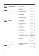
Chapter 1 Chapter 2 Chapter 3 Chapter 4 Chapter 5 Chapter 6 Product Accessories 1-1 Included Accessories 3 1-2 Optional Accessories 3 2-1 Specifications 4 2-2 Dimensions & Connections 5 3-1 Safety Precautions 6 3-2 Before Installation 7 3-3 Choosing Installation Site 8 3-4 High Elevation Installations 9 3-5 Installation Clearances 10 4-1 Securing to the Wall 13 4-2 Vent Pipe Installation 14 4-3 Setting the High Elevation 21 4-4 Gas Piping 22 4-5 Water Piping 25 4-6 Heating In
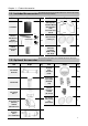
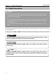
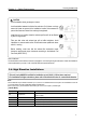
Chapter 1. – Product Accessories The following accessories are included with the unit. Check for any missing 1-1. Included Accessories items before starting installation.
Specifications Chapter 2. – Product Specifications Specifications may be changed without prior notice.The capacity may differ slightly, 2-1. Specifications depending on the water pressure, water supply, piping conditions, and water temperature. Model Name CB199-DV CB180-DV MAX 199,000 Btu/h 180,000 Btu/h MIN 18,000 Btu/h 18,000 Btu/h 35°F Rise 9.2 GPM 9.2 GPM 45°F Rise 7.7 GPM 7.2 GPM 77°F Rise 4.5 GPM 4.
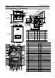
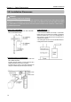
Dimensions & Connections Chapter 2. – Product Specifications 2-2. Dimensions & Connections 17.3" [440mm] 16.0" [407mm] 11.5" [292 mm] 9.3" [236mm] 7.5" [190mm] 3.8" [97mm] 2.6" [66mm] 4.6" [117mm] 2.5" [63 mm] 4.1"[105 mm] C 14.8" [377mm] A B I D H E 7.5" [191mm] 3.6" [92mm] 1.5" [37mm] G 8.3" [212mm] 9.9" [251mm] 15.0" [382mm] 15.5" [393mm] Description 28.
Chapter 3. – Safety Requirements Safety Precautions 3-1. Safety Precautions WARNING To avoid product damage, personal injury, or even possible death, carefully read, understand, and follow all the instructions in the Installation Manual and Owner’s Guide before installation, operation and service of the Combi Boiler. Noritz cannot anticipate every circumstance that might involve a potential hazard. Therefore, all possible incidents are not included in our warnings.
Chapter 3. – Safety Requirements Before Installation 3-2. Before Installation DANGER Check the fixing brackets and vent pipe yearly for damage or wear. Replace if necessary. WARNING Precautions on Vent Pipe Replacement The vent system will almost certainly need to be replaced when this appliance is being installed. Only use vent materials that are specified in this Installation Manual for use on this appliance. Refer to the “Vent Pipe Installation” section for details.
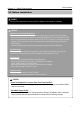
Chapter 3. – Safety Requirements Choosing Installation Site 3-3. Choosing Installation Site Locate the appliance in an area where leakage from the unit or connections will not result in damage to the area adjacent to the appliance or to the lower floors of the structure. When such locations cannot be avoided, it is required that a suitable drain pan, adequately drained, be installed under the appliance. The pan must not restrict combustion air flow.
Choosing Installation Site Chapter 3. – Safety Requirements CAUTION Avoid installation above gas ranges or stoves. Avoid installation between the kitchen fan and stove. If oily fumes or a large amount of steam are present in the installation location, take measures to prevent the fumes and steam from entering the equipment. Install the unit in a location where the exhaust gas flow will not be affected by fans or range hoods. Take care that noise and exhaust gas will not affect neighbors.
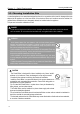
Installation Clearances Chapter 3. – Safety Requirements 3-5. Installation Clearances WARNING Before installing, check for the following: Install in accordance with relevant building and mechanical codes, as well as any local, state or national regulations, or in the absence of local and state codes, to the National Fuel Gas Code ANSI Z223.1/NFPA 54 – latest edition. In Canada, see Natural Gas and Propane Installation Code (CSA B149.1-latest edition). for detailed requirements.
Installation Clearances Chapter 3.
Installation Clearances Chapter 3.
Chapter 4. – Installation Securing to the wall 4-1. Securing to the wall WARNING CLEARANCES FOR SERVICE ACCESS The Combi Boiler must be installed on a wall that can bear its weight. If you try to install the Combi Boiler on a wall which cannot support its weight, please reconsider. The Combi Boiler can be installed on any suitable internal wall (suitable sound proofing may be required when installing onto a stud partition wall). 1.Use the wall bracket to mark two locations where the anchor 5.
Vent Pipe Installation Chapter 4. – Installation 4-2. Vent Pipe Installation (Indoor Installation Only) General Requirements • Under normal conditions, this appliance will not produce an exhaust flue temperature in excess of 149°F (65°C) and schedule 40 PVC pipe may be used as the vent material. If the Combi Boiler set temperature is 160°F (70°C) or higher, schedule 40 CPVC or PP must be used. • When using CPVC or PP, a setting must be changed in the Installer Mode [6:Vt].
Chapter 4. – Installation Vent Pipe Installation Vent Material Setting CAUTION • This Combi Boiler has a built-in control to limit the exhaust temperature to 149°F (65°C). As a result, the Combi Boiler can be vented with Schedule 40 PVC. • In high temperature applications, the exhaust temperature can exceed 149°F (65°C).
Chapter 4. – Installation Vent Pipe Installation Maximum Vent Length The unit can be adjusted to accommodate longer vent runs; refer to the below table to find the maximum vent length based on the number of elbows. Allowable Schedule 40 Vent Length (PVC, CPVC, PP) Pipe diameter No. of Elbows 3" (75mm) 2" (50mm) Max. straight Vent Length* 6 70´ N/A 5 75´ N/A 4 80´ 18´ 3 85´ 26´ 2 90´ 34´ 1 95´ 42´ 0 100´ 50´ • 5 feet (1.5M) for each additional 3-inch 90-degree elbow • 2.5 feet (0.
Chapter 4. – Installation Vent Pipe Installation Vent Pipe Installation (DV-Direct Vent) pGiGzQ GlGG`WGGl Horizontal Vent Termination- PVC/CPVC/PP Materials Only • As illustrated on the right, make sure to keep a distance of 3' (0.9m) or wider between the intake and exhaust when installing the vent piping. * If 3' (0.9m) remote distance between Intake and Exhaust cannot be ensured, the installation can be carried out only in the installation method shown in page 19.
Q S U Vent Pipe Installation Chapter 4. – Installation Vent Pipe Installation (DV-Direct Vent) Concentric PVC/CPVC Termination • PP can not be used if the concentric termination is being used. Must use PVC or CPVC. • The concentric termination may be shortened, but not lengthened from its original factory supplied length. • 2" (50mm) & 3" (75mm) PVC or CPVC pipe may be used with the concentric termination. Reducers will be needed to connect 2" pipe.
Vent Pipe Installation Chapter 4. – Installation Vent Pipe Installation (DV-Direct Vent) Horizontal Vent Termination- PVC/CPVC/PP Materials Only * When 3' (0.9m) remote distance between Intake and Exhaust cannot be ensured. * Can not use Hood termination (PVT-HL) • Intake and exhaust should face the same direction. Intake and exhaust should stay within the same pressure zone. • Insert the bird screen. 90° elbow vertical setting (downward). • Ensure at least 3ft (0.
Vent Pipe Installation Chapter 4. – Installation ZIGt Vent Pipe Installation (SV-Non Direct Vent) o z l * When supplying combustion air from the indoors (SV-CK-3 Conversion Kit is required) orizontal Vent Termination- PVC/CPVC/PP Materials H Only • A tee, the PVT-HL termination may be used for the vent termination. It is not necessary to use bird screens with the PVT-HL termination. • Terminate at least 12" (300mm) above grade or above snow line. • Terminate at least 7' (2.
Chapter 5. – Setting High Elevation 4-3. Setting the High Elevation Elevation above Sea Level 7:EL setting 0~1,999ft (0~609m) 0-2 2,000~4,999ft (610~1,523m) 2-5 5,000~7,999ft (1,524~2,438m) 5-8 8,000~10,000ft (2,439~3,048m) 8 - 10 1. Turn off the power to control panel. 3. ‘0-2’ will flash when the ‘Dial Button’ is pressed. (The default setting is ‘0-2’ for installations at 0~1,999ft elevation.) 2. Press and hold the ‘Function Button’ for 5 seconds to get into the ‘Installer Mode’.
Chapter 4. – Installation Gas Piping order to choose the proper size for the gas line, consult local codes or the National Fuel Gas 4-4. Gas Piping InCode ANSI Z223.1, CAN/CGA B149.1. CAUTION The guidelines and examples provided in this manual section are for reference only. The sizing and installation of the gas system for this Combi Boiler, as with any gas appliance, is the sole responsibility of the installer.
Gas Piping Chapter 4. – Installation CAUTION Pressure Test The appliance and its gas connections must be leak tested before placing the appliance in operation. The appliance must be isolated from the gas supply piping system by closing its individual manual shutoff valve during any pressure testing of the gas supply piping system at test pressures equal to or less than ½ psig (3.5 kPa). It is not recommended to pressure testing in excess of ½ psig (3.5kPa).
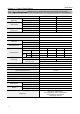
Gas Supply Piping Chapter 4. – Installation Gas Line Sizing for a Noritz Condensing Gas Combi Boiler Table 1. For Less than 8" WC initial supply pressure Maximum Natural Gas Delivery Capacity (0.
Chapter 4. – Installation Water Piping Installation must be performed by a qualified plumber. In the Commonwealth of Massachusetts, this 4-5. Water Piping product must be installed by a licensed plumber or gas fitter in accordance with the Massachusetts Plumbing and Fuel Gas Code 248 CMR Sections 2.00 and 5.00. Observe all applicable codes. This appliance is suitable for combination potable water and heating applications. Do not use this appliance if any part has been underwater.
Water Piping Chapter 4. – Installation Supply water piping DHW piping • Do not use PVC, iron, or any piping which has been treated with • Do not use lead, PVC, iron or any piping which has been treated with chromates, Combi Boiler seal or other chemicals. • Mount a check valve and a shut off valve (near the inlet). • In order for the client to use the Combi Boiler comfortably, 14 to 70 PSI (98.1 to 491kPa ) of pressure is needed from the water supply. Be sure to check the water pressure.
Chapter 4. – Installation Heating Installation 4-6. Heating Installation System Pressure The Combi Boiler is intended solely for use in pressurized closed loop heating systems operating with 12-30 psi water pressure at the Combi Boiler outlet. To obtain the minimum system design pressure, follow the piping diagrams illustrated in this section.
Chapter 4. – Installation Low Water Cutoff 4-7. Low Water Cutoff (LWCO) Internal of the Combi Boiler The Noritz Combi Boiler is equipped with a factory installed, pressure sensor type low water cutoff device. The lowest operation pressure for this device is 8psi. (operation pressure = (default valve 12psi) - (4psi)) • The Combi Boiler performs water replenishment automatically when the built-in water pressure sensor detects insufficient water level in the Combi Boiler system.
Chapter 4. – Installation Pressure Relief Valve 4-8. Pressure Relief Valve • External pressure relief valve must be installed. Observe the following. Failure to comply with the guidelines on installing the pressure relief valve and discharge piping can result in personal injury, death or substantial property damage. • DO NOT install a relief valve (DHW pipe line) with pressure higher than 150psi and relief valve (Heating pipe line) with pressure higher than 30psi.
Chapter 4. – Installation Auto Feeder Connection Auto Feeder Connection • Before filling the Combi Boiler, loosen the air vent cap to allow the system to fill properly. Tighten the cap when the system is full. Air Vent Cap Air Vent Cap • The Combi Boiler is equipped with an auto feeder valve. Therefore, installation of additional system water fill connection is not necessary in most cases. See the following figure for an example of a water fill installation using the built-in connection.
Chapter 4. – Installation External Water Feeder • External water feeder may be installed on the system piping if it is required for specific applications. See the following figure for an example of external water feeder installation on the system piping.
Condensate Piping Chapter 4. – Installation 4-9. Condensate Piping CAUTION Due to the acidic nature of the condensate, be sure to properly drain and if necessary, treat the condensate prior to disposal. Damage caused by improperly handled condensate is not covered by the warranty. • This Combi Boiler is a high efficiency, fully condensing appliance which produces acidic condensate during operation.
Electrical Wiring Chapter 4. – Installation 4-10. Electrical Wiring Do not connect electrical power to the unit until all electrical wiring has been completed. Do not connect electrical power to the unit until all electrical wiring has been completed. This appliance must be electrically grounded in accordance with local codes, or in the absence of local codes, with the National Electrical Code, ANSI/NFPA 70. In Canada, the latest CSA C22.1 Electrical Code.
Chapter 4. – Installation Application Connection 4-11. Wiring Diagram for External Options Ref: Page 36 Ref: Page 28 Ref: Pages 38-39 Ref: Pages 36-38 Note: * 1 External Pump Terminal : ‘10:EP’ should be ‘on’ in Installer Mode to activate this terminal. * 2 Air Handler Terminal : ‘8:AH’ should be ‘on’ in Installer Mode to activate this terminal.
Chapter 4. – Installation Plumbing Guidelines 4-12. Plumbing Guidelines Piping Symbol 1.This drawing is meant to show system piping concept only. Installer is responsible for all equipment and detailing required by local codes. 2. All closely spaced tees shall be within 4 pipe diameters center to center spacing. 3. A minimum of 6 pipe diameters of straight pipe shall be installed upstream and downstream of all closely spaced tees. 4.
Chapter 4. – Installation Application Diagram 1. Primary/Secondary Piping with Zone Valves 10:EP mode should to be ‘ON’ in Installer Mode to activate this terminal.
Chapter 4. – Installation Application Diagram 2.
Chapter 4. – Installation Air Handler 4-13. Air Handler The Noritz Combi Boiler can control the operation of an Air Handler when a thermistor is used in combination with the Air Handler. The Air Handler function is designed to stop the Air Handler’s pump and fan operation when the Combi Boiler's heating function is not operating due to DHW operation, Combi Boiler errors or Low Water in the Combi Boiler. • • • • • The Air Handler turns off when the following conditions arise: Thermistor open or short.
Chapter 4. – Installation Air Handler How to activate the Air Handler Terminal. 1. Turn off the power to the control panel. Press and hold the ‘Function Button’ for approximately 5 seconds to get into the ‘Installer Mode’. 3. Press the ‘Dial Button’ so ‘oFF’ is blinking. Then turn the ‘Dial Button’ clockwise so ‘on’ is blinking. 2.Turn the ‘Dial Button’ clockwise to 8:AH. 4. Press the ‘Dial Button’ to save the setting.
Chapter 4. – Installation Trial Run 4-14. Trial Run - Auto Feeder Process. 1. Turn on the power to the control panel. 2. Automatic water replenishment in progress when the Combi Boiler is less than the internal pressure 12psi. Note) ‘Error Code 54’ will be indicated at the beginning of auto feeding. This is normal operation. When auto feeding is complete, ‘Error Code 54’ turns off automatically.
Chapter 5. – Setting Outdoor Temperature Reset 5-1. Outdoor Temperature Reset The Outdoor Reset Control feature may be used to enhance energy efficiency while maintaining optimal heating performance. With the Outdoor Reset Control, the heating temperature setting automatically changes according to the outdoor temperature and the current heating system application.
Chapter 5. – Setting Outdoor Temperature Reset Setting the ‘Outdoor Temperature Reset Mode’. [2:TR] Outdoor Temperature Reset Mode 1. Connect outdoor sensor to terminal. (Refer to page 46 of the Installation Manual for additional detail) 3. Turn the ‘Dial Button’ clockwise until ‘[2:TR]’ is displayed. 2. Turn off the power to control panel. Press and hold the ‘Function Button’ for approximately 5 seconds to enter the ‘Installer Mode’. 4. Press the ‘Dial Button’. OFF will begin blinking.
Chapter 5. – Setting Outdoor Temperature Reset Adjusting Outdoor Temperature Reset Control Options 6. Turn the ‘Dial Button’ clockwise until ‘[3:TY]’ is displayed on the screen. Types of Heating Application (See below for how to select hot water heating source.) Heating Application Set point Range(°F/°C) Display Low High Note Finned Tube Baseboard A.Ftb 120°F (49°C) 180°F (82°C) Default Air Handler b.AH 140°F (60°C) 180°F (82°C) Cast Iron Baseboard C.Cib 100°F (38°C) 170°F (76.
Chapter 5. – Setting 9. With ‘4:Od’ displayed, press the ‘Dial Button’. ‘A:HI’ will begin flashing. Outdoor Temperature Reset 10. Press the ‘Dial Button’. The default design warm weather temperature (70°F) will flash on the display. Turn the ‘Dial Button’ to adjust to the desired temperature. 12. Turn the ‘Dial Button’ to ‘b:noH’. 11. Press the ‘Dial Button’ to confirm the setting. 13. Press the ‘Dial Button’. ‘b:noH’ will being to flash on the display. 14. Press the ‘Dial Button’.
Chapter 5. – Setting Outdoor Temperature Reset 15. Press the ‘Dial Button’ to confirm the setting. 16. Turn the ‘Dial Button’ until ‘C.Lo’ is displayed. ‘C.Lo’ allows for adjustment of the design low temperature setting. 17. Press the ‘Dial Button’. The default design cold weather temperature (20°F) will flash on the display. Turn the ‘Dial Button’ to adjust to the desired temperature. 18. Press the ‘Dial Button’ to confirm the setting. 19.
Chapter 5. – Setting Outdoor Temperature Reset Outdoor Temperature Sensor Installation Guidelines • Avoid areas with direct sunlight and where temperatures may not be representative of true outdoor temperature. • Avoid placing sensor in close proximity of heat sources that may affect correct temperature sensing. (fans, exhausts, vents, lights) • Avoid installing the sensor in areas where the sensor is subjected to excessive moisture. • Make sure wiring connections are secure before closing the cap.
2:TR 1:HT Select & Enter Function Primary Display Outdoor Temp Reset Heating Temp Range Function Name Primary Display 1 2 3 on oFF Lo HI Select & Enter Step 1 80 - 120°F (26 - 49°C) 121 - 180°F (49.5 - 82°C) Select & Enter Step 2 Select & Enter Step 3 Secondary Display 5-2. Installer Mode (Parameter Settings) Chapter 5.
3:TY (Skipped if 2:TR is Off) TYpe of Heating Sytem G.CUS (Customized) Lo HI Sub Default 180°F (82°C) Sub Default 100°F (38°C) 80 - 120°F (26.5 - 49°C) 120 - 170°F (49 - 76.5°C) 80 - 120°F (26.5 - 49°C) 80 - 140°F (26.5 - 60°C) 100 - 170°F (38 - 76.5°C) 140 - 180°F (60 - 82°C) Default 120 - 180°F (49 - 82°C) Default 121 - 180°F (49.5 - 82°C) (Radiator) F.rAd (Low Mass Radiant Floor) d.LrF (Mass Radiant Floor) (Cast Iron Baseboard) C.CIb E.rF (Air Handler)* b.
6:Vt (Skipped if 2:TR is oFF) 5:bS (Skipped if 2:TR is oFF) 4:Od Select & Enter Function Vent Material Boost Timing Outdoor Temp Function Name Primary Display CPVC PVC 1 - 120 min oFF C.Lo b.noH A.HI Select & Enter Step 1 -4 - 61°F (-20 - 16°C) oFF Default Default Default 20°F (-6.
9:PH 8:AH 7:EL Select & Enter Function Pre-Heating Air Handler High ELevation Function Name Primary Display on oFF on oFF 8 - 10 5 -8 2-5 0-2 Select & Enter Step 1 Select & Enter Step 2 Select & Enter Step 3 Secondary Display Default Default Default Default This function is used to preheat the internal DHW plate heat exchanger during selected times set. • After turning on this function the timer will need to be set.
13:Or 12:IV 11:WP 10:EP Pump Overrun Time Interval Water Pressure External Pump do.H HEAt 0-20 min 12 - 26 PSI on oFF Select & Enter Select & Enter Function Name Step 1 Function Primary Display 1 - 20 min 0 - 60 min Select & Enter Step 2 Select & Enter Step 3 Secondary Display Default 3 min Default 20 min Default 3 min Default Default Default This mode is to control how long the pump will run after the heating or DHW demand is satisfied.
14:bT Burner Set Temp b.on A.oFF Select & Enter Select & Enter Function Name Step 1 Function Primary Display 1 - 30°F [0.5 - 16.5°C] 0 - 30°F [0 - 16.5°C] Select & Enter Step 2 Select & Enter Step 3 Secondary Display Default 30°F (16.5°C) Default 10°F (5.5°C) Default This mode is to set the activation points for the Heating Mode. • When the internal temperature of the Combi Boiler is to high or low the unit will stop burning or start burning.
Chapter 6. - Final Check Points & Maintenance Final Check List 6-1. Final Check List Final check : On the installation conditions.
Chapter 6. - Final Check Points & Maintenance 6-2. Maintenance Maintenance Periodically check the following to ensure proper operation of the Combi Boiler.. •The venting system must be examined periodically by a qualified service technician to check for any leaks or corrosion. • The burner flame must be checked periodically for a proper blue color and consistency. • If the flame does not appear normal, the burner may need to be cleaned.
Maintenance Log Chapter 6. - Final Check Points & Maintenance MAINTENANCE LOG CAUTION In unusually dirty or dusty conditions, care must be taken to keep Combi Boiler cabinet door in place at all times. Failure to do so VOIDS WARRANTY! WARNING Allowing the Combi Boiler to operate with a dirty combustion chamber will hurt operation. Failure to clean the heat exchanger as needed by the installation location could result in Combi Boiler failure, property damage, personal injury, or death.
Memo 56
Memo 57
Memo 58
Memo 59
Installation Manual NORITZ AMERICA CO.