Owner’s Guide CONDENSING TANKLESS GAS WATER HEATER Model : NCC199CDV (GQ-C3260WZ-FF US) Thank you for purchasing this Noritz Tankless Gas Water Heater. Before using: • Read this manual completely for operation instructions. • Completely fill out the warranty registration card (included separately) and mail the detachable portion to Noritz America Corporation. • Keep this manual (and the remainder of the warranty registration card) where it can be found whenever necessary.
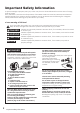
Important Safety Information To prevent damage to property and injury to the user, the icons shown below will be used to warn of varying levels of danger. Every indication is critical to the safe operation of the Water Heater and must be understood and observed. Potential dangers from accidents during installation and use are divided into the following four categories. Closely observe these warnings; they are critical to your safety. Icons warning of risk level This is the safety alert symbol.
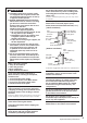
WARNING A. This Water Heater does not have a pilot. It is equipped with an ignition device that automatically lights the burner. Do not try to light the burner by hand. B. BEFORE OPERATING smell all around the Water Heater area for evidence of leaking gas. Be sure to smell next to the floor because some gas is heavier than air and will settle on the floor. WHAT TO DO IF YOU SMELL GAS • Do not try to light any appliance. • Do not touch any electrical switch; do not use any phone in your building.
WARNING Be sure the gas/power supplied matches “Type of Gas” and “Electrical Rating” on the rating plate. (e.g. NCC199CDV (GQ-C3260WZ-FF US)) [When supplying combustion air from the indoors] Check the air supply opening for dust or obstructions. To prevent injury or death, do not allow small children to bathe or play in the bathroom unsupervised. Do not touch the power cord with wet hands. Contact a qualified service technician for any necessary repairs, service or maintenance.
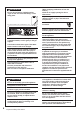
NOTICE Do not disassemble the Remote Controller. Do not drink water that has been inside the appliance for an extended period of time. Do not drink the first use of hot water from the appliance in the morning. Do not use chlorine-based, acidic, alkaline detergents, organic solvents such as benzine and thinner, or Melamin Sponge to clean the Remote Controller. This may cause discoloration, deformation, scratches or cracks.
Contents Important Safety Information................ 2 Contents................................................ 6 General Parts......................................... 7 Water Heater......................................... 7 Remote Controller................................. 8 Initial Operation....................................10 Clock Adjustment..................................11 Using the Water Heater.........................12 Setting Hot Water Temperature.............
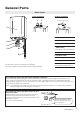
General Parts Water Heater Indoor Installation 1 2 Outdoor Installation Outdoor Vent Cap 3 1. Intake Pipe 2. Exhaust Pipe 4 7 5 6 8 9 3. Front Cover 4. Water Drain Valve (with Water Filter) Inside Water Inlet (See page 29) 5. Pressure Relief Valve 6. Hot Water Valve 7. Water Supply Valve 8. Gas Supply Valve This illustration shows an example of installation. The exact installation configuration may be slightly different. 9. Condensate Drain Pipe Discharge the condensate.
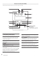
Remote Controller (RC-9018M) The Remote Controller will emit a tone when a button is pressed. 2 3 1 4 5 6 10 7 11 8 Remote Controller Part Number The part number is printed on the surface of the cover. 9 Cover shown in the open position. 1. Power Button / Indicator (Green) For turning the Water Heater ON/OFF. 2. PROG Button / Indicator (Red) Activate the automatic Water Heater power ON/ OFF setting as determined by the user selected schedule. (See page 14) 3.
Display Screen • The display screen shown below is for illustration purposes only. The actual display will vary depending on how the Water Heater is being used. • After a button is pressed, the display will gradually become darker to prevent unnecessary power consumption by the Remote Controller. 1 7 2, 3 8 4 5, 6 9 1. Flame Indicator The flame indicator is displayed during combustion when using hot water or recirculation functions. 7.
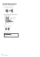
Initial Operation Before the first use, do the following: 1. Open the water supply valve. CLOSED OPEN 2. Open a hot water fixture/faucet to confirm that water is available, and then close the fixture/faucet again. Hot water fixture/faucet 3. Open the gas supply valve. 4. Turn on the power. WARNING Do not touch the power cord with wet hands.
Clock Adjustment Operation 1. Press the MENU button inside the cover. • This adjustment can be made whether the Power button is ON/OFF. 2. Press the ENTER button. 3. Use the / buttons to reset the clock. (e.g. 10:15 am) • The time changes in 1 minute increments with each press of the button, and then in 10 minutes increments if the button is pressed and held. 4. Press the the ENTER button to complete the clock setting. The screen returns to the previous screen.
Using the Water Heater If “System [ Tank ]” is displayed, hot water will be discharged at the temperature of the storage tank. (See page 20) Operation 1. The Power button is ON. For systems with recirculation operation, is displayed here. Check (e.g. 110°F) • The Power indicator is displayed. • The previously set hot water supply temperature is shown. • The setting temperature displayed may vary from the actual temperature at the fixture depending on conditions such as season or length of piping.
Setting Hot Water Temperature If “System [ Tank ]” is displayed, hot water will be discharged at the temperature of the storage tank. (See page 20) Operation The temperature settings below are examples. The temperature setting necessary depends on the usage, the length of piping and the season. [When using °F mode] (Default setting is 110°F) 1. The Power button is ON. (e.g. 110°F) • The Power indicator is displayed. • The previously set hot water supply temperature is shown. 2.
Automatic Water Heater ON or OFF Operation • If you set the time to turn ON or OFF the Power button, the Power button is automatically turned ON or OFF at the set time every day by just turning the PROG button ON. • It is also possible to set only ON or OFF operation. • For recirculation systems, circulation is started or stopped according to the Power button condition, ON or OFF. 6. Press the ENTER button to complete the setting. 7. Set the OFF time to “PM 8:00” using the buttons.
Deactivate Automatic Operation The PROG button is OFF. • The PROG indicator disappears. NOTE • If the PROG button is not set to OFF, the Water Heater will automatically turn ON or OFF at the set times. • If there is a power failure or power is disconnected to the Water Heater, automatic operation will be deactivated. Tips for operation Following this procedure allows for automated control of Water Heater operation without user interaction.
Locking the Remote Controller By locking the Remote Controller, the settings cannot be changed if a button is pressed by mistake. Operation 1. Press and hold Lock button for approximately 2 seconds to lock the Remote Controller. • This adjustment can be made whether the Power button is ON/OFF. • The operations of PROG button, MENU button, and / buttons are locked. • Approximately 3 seconds after locking the Remote Controller, the display will return to the previous screen. 2.
Customizable Settings Limiting the Maximum Output Temperature The maximum output temperature can be limited to prevent discharging hot water at too high of a temperature. Display Screen Power Saving Mode [powersave dsply] To conserve power consumption of the display, the screen can be turned off completely or set to only display the clock when the Power button is turned OFF.
Muting the Remote Controller The Remote Controller can be muted so that it does not emit a tone when a button is pressed. (For Multi-System Only) Error Tone Settings The Remote Controller can be muted so that it does not emit a tone when an error occurs. Draining the Water Heater (Refer to page 26 for details.) Operation Operation Operation 1. Press the MENU button inside the cover, select “Misc settings” using the / buttons. 1.
(Single Water Heater only) Flow Meter Alarm The flow meter alarm is being used to indicate when a tub is full. Operation 1. The Power button is ON. • Check the current setting temperature. 2. Press the MENU button inside the cover, select “Flow meter” using the / buttons. 3. Press the ENTER button. • The “Flow meter” screen appears. 4. Change the volume using the / buttons, and then press the ENTER button. NOTE • The hot water filling temperature is same as the setting temperature.
System Check • Depending on the configuration of your system, not all functions may be used. • If you press the STATUS button, you can check the status of the system. (Display Example [System [ Rcrc ] ]) • The pictures below (the number of Water Heaters, fixtures, and pumps) will vary depending on the configuration of the hot water system. Display “System [ Std ]” on the Remote Controller The Water Heater only operation. (Functions other than those shown on pages 21 to 24 can be used.
For “System [ Rcrc ]” Enabling Automatic Recirculation Operation • To check system status, see page 20. • When “Synchro ON/OFF” is set to Yes, recirculation can be activated automatically. • To change “Synchro ON/OFF” from Yes to No, follow the same procedure as described below. Operation 1. Press the MENU button inside the cover, select “Recirc menu” using the / buttons. • This adjustment can be made whether the Power button is ON/OFF. 2. Press the ENTER button. 3.
For “System [ Rcrc ]” anually Starting Recirculation M Operation Recirculation operation can be manually stopped or started using this procedure. Operation 1. The Power button is ON. (e.g. 110°F) • The Power indicator is displayed. • The previously set hot water supply temperature is shown. 2. Press the MENU button inside the cover, select “Recirc menu” using the / buttons. 3. Press the ENTER button. 4. Select “Recirc on/off” using the / buttons. 5. Press the ENTER button.
For “System [ Rcrc ]” etting the Recirculation S System Operation Timer • With the recirculation operation timer set, hot water will be automatically circulated in the hot water pipes. Even with this function activated, it may take several minutes for hot water to be completely circulated through the plumbing system. Set the timer to activate the recirculation system prior to the first use of hot water to ensure hot water is instantly available. • Multiple recirculation time periods can be set.
10. Press the ENTER button to complete the time setting. Reset All Time Periods 1. After step 9 on page 23, select “Reset” using the / buttons. “Recirc timer” and “Recirc timer on” are alternately displayed on the menu (approximately 10 seconds) Displayed (Example of home screen when the Power button is turned ON) • The timer will not activate without pressing the ENTER button. • If the time is not set, the time setting screen is displayed (See page 11).
Preventing Damage from Freezing NOTICE • Damage can occur from frozen water within the appliance and pipes even in warm environments. Be sure to read below for appropriate measures. • Repairs for damage caused by freezing are not covered by the warranty. Freezing is prevented within the device automatically by the freeze prevention heater. Freezing cannot be prevented when the power plug is unplugged. Do not remove the power plug from the wall outlet.
If the Water Heater will not be used for a long period of time, drain the water. Manual Draining 1. Close the gas valve. WARNING • To prevent burns or scalding, turn off the Power button and wait until the appliance cools before draining the water • Do not touch the power cord with wet hands. • To prevent damage from freezing, the Water Heater must be plugged into power at all times. If power is unplugged, drain the water completely from the Water Heater.
Turning the Water Heater Back On DANGER After the Water Heater has been out of use for a long time, make sure that you fill the condensate trap with water. This is to prevent dangerous exhaust gases from entering the building. Failure to fill the condensate trap could result in severe personal injury or death. (By performing step 4 as described below, the condensate trap will automatically fill itself with water.) WARNING Do not touch the power cord with wet hands. 1.
Regular Maintenance Periodic Inspection Periodic check and maintenance should be performed once a year by a qualified service technician to assure that all the equipment is operating safely and efficiently. We recommend to make necessary arrangements with a service contractor. WARNING To prevent burns or scalding, turn off the Power button and wait until the appliance cools before performing maintenance. A Check : C • For abnormal sounds during operation.
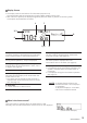
Water Drain Valve (with Water Filter) If the water drain valve (with water filter) is covered with debris, the hot water may not run smoothly, or the Water Heater may put out cold water. Check and clean the filter as explained below. WARNING To prevent burns or scalding, turn off the Power button and wait until the appliance cools before draining the water. 1. Close the hot water valve and the water supply valve. O-Ring Hot water valve Water supply valve Water drain valve with water filter 2.
Troubleshooting Initial Operation Temperature The Water Heater does not attempt to ignite when water is running. • Check for reversed plumbing or crossed pipes. • Check the water filter. (See page 29) Hot water is not available when a fixture is opened.
Fluctuations in hot water temperatures. • Set water temperature at 115°F to 120°F or 48°C (118°F) to 50°C (122°F). This will allow you to use a higher flow of hot water thus meeting the minimum flow requirement of 0.29 GPM (1.1 L/ min)*. *Minimum activation flow rate: 0.5 GPM (2.0 L/min) Minimum operating flow rate: 0.29 GPM (1.1 L/min) • Clean the water filter of any debris (See page 29) Setting temperature cannot rise.
Checking for Error Conditions When a failure occurs, information relating to the error blinks on the display. The error alarm may also continuously sound. If this occurs, take appropriate measures as following list. [Error Code Display Screen] Error Code : 90 Cause : [ When supplying combustion air from the indoors] The air supply vent may be clogged. Action : Check air supply vent for blockage or obstruction.
Follow-up Service Requesting Service First follow the instructions in the troubleshooting section. (See page 30-32) If the error is not corrected, contact Noritz America Technical Support at 1-866-766-7489. We will need to know: • The Model Check the rating plate (See page 4 for the location of the label) • Date of purchase See the warranty • Details of problem Flashing error codes, etc.
Check the status of the system 1.Press the STATUS button inside the cover. (Display Example) • Status can be checked regardless of whether the Power button is ON/OFF. • If you press the BACK button or it is left untouched for approximately 10 minutes, it will return to the previous screen. 2.Press the STATUS button inside the cover again. (Display Example) • You can Identify units that require service. (system dependent) • If you press the BACK button, the screen returns to STEP 1.
1. Before the gas conversion is performed, verify the proper gas conversion kit with your Water Heater model on the table provided below. Conversion Kit CK-82 CK-83 Conversion Type Propane to Natural Gas Natural Gas to Propane 2. The following parts are supplied in the conversion kit. These items will replace the existing parts that are currently installed in the Water Heater.
Specifications • Specifications may be changed without prior notice. • The capacity may differ slightly, depending on the water pressure, water supply, piping conditions, and water temperature. Item Specification NCC199CDV (GQ-C3260WZ-FF US) Installation Indoor / Outdoor Wall mounted Type Air Supply / Exhaust Power Vented Ignition Direct Ignition 15-150 psi Operating Pressure (Recommended 50 to 80 psi for maximum performance) Minimum Activation Flow Rate* 0.5 GPM (2.0 L/min) Minimum Operating Flow Rate* 0.