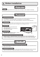
Installation Manual NORITZ AMERICA CORPORATION TANKLESS GAS WATER HEATER NR83-DVC (Indoor Installation) Potential dangers from accidents during installation and use are divided into the following three categories. Closely observe these warnings, they are critical to your safety. DANGER WARNING CAUTION DANGER indicates an imminently hazardous situation which, if not avoided, will result in death or serious injury.
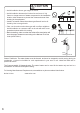
1. Included Accessories Shape Part Part 5 Owner's Guide, Warranty, Installation Manual (this document) 2. Optional Accessories Shape 1 (includes pressure relief valve) 4"-CVP-4STR 12"-CVP-12STR 24"-CVP-24STR 36"-CVP-36STR 11"-CVP-11ADJ 16"-CVP-16ADJ 40"-CVP-40ADJ Shape Part Q’ty Part No. Description Pipe Cover (PC-2S) Part No. Description 1 Part No.
. Quick Connect Multi System Installation • The Quick Connect Multi System allows the installation of two units together utilizing only the Quick Connect Cord. The Quick Connect Cord is 6' (2m) long. Install the units 2-18" (50-450mm) apart from each other to ensure the cord will be able to reach between the units. (See Typical Plumbing diagram).
. Before Installation DANGER Checkup • Check the fixing brackets and vent pipe yearly for damage or wear. Replace if necessary. WARNING Precautions on Vent Pipe • This appliance requires the use of special concentric type vent pipe specified by Noritz America. Do not attempt to use materials that are not specified for use on this appliance. Improper venting may result in a fire, property damage, or exposure to Carbon Monoxide.
. Choosing Installation Site * Locate the appliance in an area where leakage from the unit or connections will not result in damage to the area adjacent to the appliance or to the lower floors of the structure. When such locations cannot be avoided, it is recommended that a suitable drain pan, adequately drained, be installed under the appliance. The pan must not restrict combustion air flow.
CAUTION • Avoid installation above gas ranges or stoves. • Avoid installation between the kitchen fan and stove. If oily fumes or a large amount of steam are present in the installation location, take measures to prevent the fumes and steam from entering in the equipment. Prohibited • Install in a location where the exhaust gas flow will not be affected by fans or range hoods. • Take care that noise and exhaust gas will not affect neighbors.
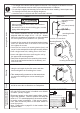
6. Installation Clearances WARNING Before installing, check for the following: Install in accordance with relevant building and mechanical codes, as well as any local, state or national regulations, or in the absence of local and state codes, to the National Fuel Gas Code ANSI Z223.1/NFPA 54 – latest edition. In Canada, see NSCNGPIC for detailed requirements. Distance from combustibles Item Check Illustration • Maintain the following clearances from both combustible and non-combustible materials.
Clearance Requirements from Vent Terminations to Building Openings * All clearance requirements are in accordance with ANSI Z21.10.3 and the National Fuel Gas Code, ANSI Z223.1 and in Canada, in accordance with NSCNGPIC.
Be sure to do Item • The weight of the device will be applied to the wall. If the strength of the wall is not sufficient, reinforcement must be done to prevent the transfer of vibration. • Do not drop or apply unnecessary force to the device when installing. Internal parts may be damaged and may become highly dangerous. • Install the unit on a vertical wall and ensure that it is level. Check Illustration mounting bracket (upper) mark (0.
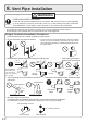
8. Vent Pipe Installation WARNING Be sure to do CARBON MONOXIDE POISONING Follow all vent system requirements in accordance with relevant local or state regulation, or, in the absence of local or state code, in the U.S. to the National Fuel Gas Code ANSI Z233.1/NFPA 54 – latest edition, and in Canada, in accordance with NSCNGPI. • This appliance requires the use of special concentric type vent pipe specified by Noritz America.
Maximum Vent Length Adjustment Connector The unit can be adjusted to accommodate longer vent runs; refer to the below table to find the maximum vent length based on the number of elbows. Adjust the dip switches according to the vent condition noted in the tables below. Note: By default, the unit has been set to the "minimum length" condition. When adjusting the dip switches for longer vent runs, the BTUH input of the appliance will be reduced by up to 8%.
• Exceeding the maximum vent length is dangerous and may result in bad combustion. • Install the vent terminal so that all exhaust is directed to and all intake air is taken from outdoors. • Do not store hazardous or flammable substances near the vent terminal. • Slope the vent pipe 1/4" (6mm) for every 12" (300mm) either towards the horizontal termination or towards the integrated condensate collector.
Vertical Vent Termination 5' (1.5m) or more Rain Cap Air Intake Pipe Roof Flashing (Base and Adapter) Firestop/ Support Hanger Strap Firestop Elbow Slope vent Upwards Drain condensate according to local codes. * Condensate collector must be used if the vertical run exceeds 3' (0.9m). • Terminate at least 6' (1.8m) from the combustion air intake of any appliance, and 3' (0.9m) from any other building opening, gas utility meter, service regulator etc.
9. Gas Piping Follow the instructions from the gas supplier. The appliance and its individual shutoff valve must be disconnected from the gas supply piping system during any pressure testing of that system at test pressures in excess of 1⁄2 psig (3.5 kPa). The Appliance must be isolated from the gas supply piping system by closing its individual manual shutoff valve during any pressure testing of the gas supply piping system at test pressures equal to or less than 1⁄2 psig (3.5 kPa).
Gas Line Sizing for a Noritz Tankless Gas Water Heater Adapted from UPC 1997 Maximum Natural Gas Delivery Capacity in Cubic Feet per Hour (0.60 Specific Gravity, 0.5" WC Pressure Drop) Pipe Size 1/2" 3/4" 1" 1 1/4" 1 1/2" 2" 2 1/2" 3" 3 1/2" 4" Length in Feet 10' (3m) 20' (6m) 30' (9m) 40' (12m) 50' (15m) 60' (18m) 70' (21m) 80' (24m) 90' (27m) 100' (30m) 125' (37.
10. Water Piping Installation and service must be performed by a qualified plumber. In the Commonwealth of Massachusetts, this product must be installed by a licensed plumber or gas fitter in accordance with the Massachusetts Plumbing and Fuel Gas Code 248 CMR Sections 2.00 and 5.00. Observe all applicable codes. This appliance is suitable for potable water and space heating applications. Do not use this appliance if any part has been underwater.
Supply water piping • Do not use PVC, iron, or any piping which has been treated with chromates, boiler seal or other chemicals. • Mount a check valve and a shut off valve (near the inlet). • In order for the client to use the water heater comfortably, 98.1 to 491 kPa (14 to 70 PSI) of pressure is needed from the water supply. Be sure to check the water pressure. If the water pressure is low, the water heater cannot perform to its full capability, and may become a source of trouble for the client.
Water Treatment This water heater is equipped with an optional automatic service *reminder function to alert the user * Do not change any other dipswitches. Do not change any other dipswitches. when flushing or a cartridge/filter change is required. Once activated, the unit will display an "05" error code on the remote controller when maintenance is due. The service interval can be set for either 6, 12, or 24 months; refer to page 19 for recommended flushing intervals.
If this water heater will be installed in an application where the supply water is hard, the water must be treated with either the Noritz H2Flow or ScaleShield or a water softener. Refer to the below tables for suggested treatment and maintenance measures to be taken based on the water hardness level. Damage to the water heater as a result of water in excess of 12 gpg (200 mg/L) of hardness is not covered by the Noritz America Limited Warranty.
11. Plumbing Applications Recirculation System NORITZ Tankless Gas Water Heater Notes: 1. Size the pump to provide a maximum of 2 GPM (7.5 L/min.) through the system at 10 ft (3m) of head plus piping losses. Adjust the flow using a globe valve and verify the flow rate with the maintenance monitors. 2. Pump Control Signal is the preferred method to control the recirculation pump. For pumps larger than 85W, a relay connection must be used.
12. Electrical Wiring Consult a qualified electrician for the electrical work. Do not connect electrical power to the unit until all electrical wiring has been completed. Disconnect Power This appliance must be electrically grounded in accordance with local codes, or in the absence of local codes, with the National Electrical Code, ANSI/NFPA 70. In Canada, the latest CSA C22.1 Electrical Code. Caution: Label all wires prior to disconnection when servicing controls.
Changing Other Features Adjusting the Temperature Display Note: The setting must be done within the first 10 minutes of connecting electrical power to the water heater. Table of Setting Items Item No. Item 12 Celsius/Fahrenheit display mode. Choices (factory defaults shaded) °F (Fahrenheit) °C (Celsius) Remote Controller Setting Button Display Power On/Off Button Flow Meter Alarm Set buttton Setting Procedure 1. Turn the water heater off by pressing the Power On/Off Button on the remote controller.
Operation Panel * The water heater has been factory set to allow a maximum temperature setting of 120 °F (50 °C). To access higher temperature settings through the remote controller, follow the below steps. 1. Turn the water heater off by pressing the ON/OFF button on the remote controller. 2. Press and hold the FLOW METER ALARM SET button until a sound is heard (2 sec.) and 120 °F (50 °C) appears on the display. 3.
Pump Wiring * This feature is not available when using the Quick Connect Multi System feature. Connecting the pump control wire PUMP 1. Leave enough slack so that the pump control wires will stay connected if the unit is removed from the wall. 2. Remove the front cover of the heater (4 screws). 3. Cut off the connector at the end of the pump control wires. 4.
Connecting Quick Connect Cord-2 For Quick Connect Multi System Installation use part #QC-2 only. (sold separately). Caution The wire coloring on the Quick Connect Cord-2 will not be the same as the wire coloring of the connection plug inside the unit. * The remote controller can be connected to either unit A or B. Do not connect a remote controller to both units. * Disconnect the remote controller from either unit A or B prior to installing the Quick Connect Cord. Quick Connect Cord-2 1.Red 2.Black 3.
13. Maintenance Periodically check the following to ensure proper operation of the water heater. • The venting system must be examined periodically by a qualified service technician to check for any leaks or corrosion. • The burner flame must be checked periodically for a proper blue color and consistency. • If the flame does not appear normal, the burner may need to be cleaned. • If the burner needs to be cleaned, it must be performed by a qualified service technician.
CAUTION Handling after trial operation • If the unit will not be used immediately, close off all gas and water shutoff valves, drain all of the water out of the unit and the plumbing system to prevent the unit and system from freezing, and bleed the gas out of the gas line. Freezing is not covered by the warranty. WARNING A fire or explosion may result if these instructions are not followed, which may cause lose of life, personal injury or property damage.
15. Dimensions NR83-DVC 13.2" (336mm) 0.4" - 1.8" (10 - 45mm) 6 - 0.2" x 0.4" (6 x10mm) OBLONG HOLE 1.1" (28mm) 4.0" (102mm) 4.4" (113mm) 1.0" (26mm) 4.8" (121mm) 5.5" (140mm) 3.9" (100mm) 2.8" 70mm) 1.4" (36mm) 9.4" (240mm) Ø5.0" (Ø127mm) Ø3.1" (Ø79mm) 13.8" (350mm) 13.1" (334mm) FLUE COLLAR AIR INLET CONDENSATE DRAIN 23.6" (600mm) 22.3" (567mm) 0.4" - 1.8" (10 - 45mm) 2.0" (50mm) 3.3" (85mm) 4.7" (120mm) GAS INLET WIRING THROUGHEAY (AC120V) 2 - 0.3" x 0.5" (6.