Installation Manual NORITZ AMERICA CORPORATION CONDENSING TANKLESS GAS WATER HEATER NRC711-DV (Indoor Installation) Potential dangers from accidents during installation and use are divided into the following three categories. Closely observe these warnings, they are critical to your safety. DANGER WARNING CAUTION DANGER indicates an imminently hazardous situation which, if not avoided, will result in death or serious injury.
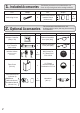
1. Included Accessories Part Shape Anchoring Screw Q’ty Part 5 Owner's Guide, Warranty, Installation Manual (this document) 2. Optional Accessories Shape The following accessories are included with the unit. Check for any missing items before starting installation. Shape Q’ty 1 each The accessories listed below are not included with the units, but may be necessary for installation. Shape Q’ty Part Remote Controller (See p.
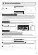
. Before Installation DANGER Checkup • Check the fixing brackets and vent pipe yearly for damage or wear. Replace if necessary. WARNING Precautions on Vent Pipe Replacement • The vent system will almost certainly need to be replaced when this appliance is being installed. Only use vent materials that are specified in this Installation Manual for use on this appliance. Refer to the "Vent Pipe Installation" section for details.
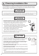
. Choosing Installation Site * Locate the appliance in an area where leakage from the unit or connections will not result in damage to the area adjacent to the appliance or to the lower floors of the structure. When such locations cannot be avoided, it is recommended that a suitable drain pan, adequately drained, be installed under the appliance. The pan must not restrict combustion air flow.
CAUTION • Avoid installation above gas ranges or stoves. • Avoid installation between the kitchen fan and stove. If oily fumes or a large amount of steam are present in the installation location, take measures to prevent the fumes and steam from entering in the equipment. Prohibited • Install in a location where the exhaust gas flow will not be affected by fans or range hoods. • Take care that noise and exhaust gas will not affect neighbors.
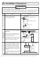
5. Installation Clearances WARNING Before installing, check for the following: Install in accordance with relevant building and mechanical codes, as well as any local, state or national regulations, or in the absence of local and state codes, to the National Fuel Gas Code ANSI Z223.1/NFPA 54 – latest edition. In Canada, see NSCNGPIC for detailed requirements. Distance from combustibles Item Check Illustration • Maintain the following clearances from both combustible and non-combustible materials.
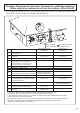
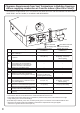
Clearance Requirements from Vent Terminations to Building Openings * All clearance requirements are in accordance with ANSI Z21.10.3 and the National Fuel Gas Code, ANSI Z223.1 and in Canada, in accordance with NSCNGPIC.
Clearance Requirements from Vent Terminations to Building Openings * All clearance requirements are in accordance with ANSI Z21.10.3 and the National Fuel Gas Code, ANSI Z223.1 and in Canada, in accordance with NSCNGPIC.
6. Installation Securing to the wall Be sure to do Item • The weight of the device will be applied to the wall. If the strength of the wall is not sufficient, reinforcement must be done to prevent the transfer of vibration. • Do not drop or apply unnecessary force to the device when installing. Internal parts may be damaged and may become highly dangerous. • Install the unit on a vertical wall and ensure that it is level.
Filling the condensate trap with water DANGER When initial start up, make sure that you perform the following procedures. This is to prevent dangerous exhaust gases from entering the building. Failure to following procedure could result in severe personal injury or death. After installing the drain pipe, make sure that the area around the unit is well ventilated; open a window or a door if necessary. Then, operate the unit and verify that condensate is coming out of the drain pipe.
7. Vent Pipe Installation (Indoor Installation Only) WARNING Be sure to do CARBON MONOXIDE POISONING Follow all vent system requirements in accordance with relevant local or state regulation, or, in the absence of local or state code, in the U.S. to the National Fuel Gas Code ANSI Z233.1/NFPA 54 – latest edition, and in Canada, in accordance with NSCNGPI.
Maximum Vent Length Adjustment DIP switch The unit can be adjusted to accommodate longer vent runs; refer to the below table to find the maximum vent length based on the number of elbows. Adjust the DIP switch according to the vent condition noted in the tables below. Note: By default, the unit has been set to the "short length" condition. When adjusting the DIP switch for longer vent runs, the BTUH input of the appliance will be reduced by up to 5%.
Venting With PVC or CPVC This appliance can be vented with non cellular core plastic pipe materials as specified in the below table. Vent installations in Canada which utilize plastic vent systems must comply with ULC S636.
Vent Pipe Installation Horizontal Vent Termination- PVC/CPVC Materials Only • As illustrated on the left, make sure to keep a distance of 3' (0.9m) Hanger Straps Intake Insert Bird Screen* in End of 90 Elbow or wider between the intake and exhaust when installing the vent piping. * If 3’ (0.9m) remote distance between Intake and Exhaust cannot be ensured, the installation can be carried out only in the installation method shown in page 16.
Horizontal Vent Termination- 3" (75mm) Concentric PVC/CPVC Termination • The concentric termination may be shortened, Intake Hanger Straps Strap Exhaust Slope vent Upwards but not lengthened from its original factory supplied length. The concentric termination may only be used 1" (25mm) to for horizontal terminations. 4" (100mm) • 3" (75mm) PVC or CPVC pipe may be used with the concentric termination.
Vent Pipe Installation Horizontal Vent Termination- PVC/CPVC Materials Only * When 3’ (0.9m) remote distance between Intake and Exhaust cannot be ensured. * Can not use Hood termination (PVT-HL) • Intake and exhaust should face the same direction. Intake and exhaust should keep the same pressure zone. 5.9” Exhaust Intake • Insert the bird screen. 90° elbow vertical setting (downward). 2ft. Min • Ensure at least 3ft (0.
Vent Pipe Installation (When supplying combustion air from the indoors (SV, non-direct vent)) DANGER When installing this water heater in an area with a large amount of lint such as a commercial Laundromat, direct-vent ("-DV") system must be used. The "-SV" configuration (using an SV conversion kit) is prohibited. • Disconnect power to the water heater before changing the DIP switch. Failure to perform this step will result in a "733" code displayed on the Display Window and a cease in operation.
Combustion Air Supply combustion air to the units as per the National Fuel Gas Code, ANSI Z223.1 and in Canada, in accordance with CSA-B149.1. • Provide two permanent openings to allow circulation of combustion air. • Make each opening 180 square inches if they provide indoor air, and 100 square inches for outdoor air. • If the unit is installed in a mechanical closet, provide a 24" (600mm) clearance in front of the unit to the door.
8. Gas Piping Follow the instructions from the gas supplier. CAUTION The guidelines and examples we have provided in this manual section are for reference only. The sizing and installation of the gas system for this water heater, as with any gas appliance, is the sole responsibility of the installer. The installer must be professionally trained to do such work and must always follow all local and national codes and regulations. Gas line sizing calculations must be performed for every installation.
WARNING Pressure Test The appliance and its gas connections must be leak tested before placing the appliance in operation. The appliance must be isolated from the gas supply piping system by closing its individual manual shutoff valve during any pressure testing of the gas supply piping system at test pressures equal to or less than ½ psig (3.5 kPa). We do not recommend pressure testing in excess of ½ psig (3.5kPa).
Table 1. For Less than 8” WC initial supply pressure Maximum Natural Gas Delivery Capacity (0.
Table 3. Maximum Undiluted Propane (LP) Delivery Capacity in Thousands of BtuH (0.
9. Water Piping Installation and service must be performed by a qualified plumber. In the Commonwealth of Massachusetts, this product must be installed by a licensed plumber or gas fitter in accordance with the Massachusetts Plumbing and Fuel Gas Code 248 CMR Sections 2.00 and 5.00. Observe all applicable codes. This appliance is suitable for combination potable water and space heating applications. It cannot be used for space heating applications only.
Hot water piping • Do not use lead, PVC, iron or any piping which has been treated with chromates, boiler seal or other chemicals. • The longer the piping, the greater the heat loss. Try to make the piping as short as possible. • Use mixing valves with low water resistance. Use shower heads with low pressure loss. • If necessary, use a pump or other means to ensure that the supply water pressure to the inlet of the heater does not fall below 29 PSI when the maximum amount of water is being demanded.
Water Treatment If this water heater will be installed in an application where the supply water is hard, the water must be treated with either the Noritz H2Flow or ScaleShield or a water softener. Refer to the below tables for suggested treatment and maintenance measures to be taken based on the water hardness level. Damage to the water heater as a result of water in excess of 12 gpg (200 mg/L) of hardness is not covered by the Noritz America Limited Warranty.
10. Condensate Piping CAUTION Due to the acidic nature of the condensate, be sure to properly drain and if necessary, treat the condensate prior to disposal. Damage caused by improperly handled condensate is not covered by the warranty. • This water heater is a high efficiency, fully condensing appliance which produces acidic condensate during operation. The water heater incorporates a collection and removal system which must be properly drained in order to ensure proper operation of this appliance.
Condensate piping to floor drain Condensate piping with pump Display window Display window USE NON-CORROSIVE MATERIALS DO NOT REDUCE TO LESS THAN 1/2” KEEP AS SHORT AS POSSIBLE USE NON-CORROSIVE MATERIALS DO NOT REDUCE TO LESS THAN 1/2” KEEP AS SHORT AS POSSIBLE 1/2" PVC pipe DO NOT ADD ANY VALVES Slope pipe downwards 1/4" per foot. or more. 1/2" PVC pipe DO NOT INSERT THE END OF DRAIN PIPE INTO THE FLOOR DRAIN. Floor drain * MAINTAIN CLEARANCE The end of the drain pipe must have an air gap.
11. Plumbing Applications Recirculation System NORITZ Condensing Tankless Gas Water Heater Notes: 1. Size the pump to provide a maximum of 1.5GPM (5.7L/min.) through the system at 10ft (0.3m) of head plus piping losses. Adjust the flow using a globe valve and verify the flow rate with the maintenance monitors. 2. Set the Aquastat to 10˚F below the set output temperature. 3. Noritz recommends the use of an Isolation Kit with the installation.
12. Electrical Wiring Consult a qualified electrician for the electrical work. Do not connect electrical power to the unit until all electrical wiring has been completed. Disconnect Power This appliance must be electrically grounded in accordance with local codes, or in the absence of local codes, with the National Electrical Code, ANSI/NFPA 70. In Canada, the latest CSA C22.1 Electrical Code. Caution: Label all wires prior to disconnection when servicing controls.
Adjusting Set Temperature • This unit can be programmed so that it will default to one of four temperatures if the optional remote controller is not used [140 °F (60 °C), 135 °F (57 °C), 130 °F (55 °C), 120 °F (50 °C)]. To change the default temperature, adjust the DIP switches as described below. The default temperature is 120 °F (50 °C). 1. Disconnect electrical power to the water heater. 2. Remove the front cover of the water heater (4 screws). 3. Disconnect the optional remote controller.
Connecting Remote Controller Cord to Unit • • • • Keep the remote controller cord away from the freeze prevention heaters in the unit. Tie the redundant cord outside the water heater. Do not put the extra length inside the equipment. The remote controller cord can be extended up to 83' (25m) with 18AWG wire. Use a Y type terminal with a resin sleeve. (Without the sleeve, the copper wire may corrode and cause problems). • Be sure to hand tighten when screwing to the terminal block.
13. Maintenance Periodically check the following to ensure proper operation of the water heater. • The venting system must be examined periodically by a qualified service technician to check for any leaks or corrosion. • The burner flame must be checked periodically for a proper blue color and consistency. • If the flame does not appear normal, the burner may need to be cleaned. • If the burner needs to be cleaned, it must be performed by a qualified service technician.
WARNING A fire or explosion may result if these instructions are not followed, which may cause lose of life, personal injury or property damage. Lighting Instructions This water heater does not have a pilot. It is equipped with an ignition device that automatically lights the burner. Do not try to light the burner by hand. 1. Read the safety information in the installation manual or on the side of the water heater. 2. Turn off all electrical power to the unit. 3.
15. Dimensions < inch (mm) > 13.3" (338mm) 4-φ0.5" (φ13mm) 2-0.3"×0.5" (6.5×13mm) OBLONG HOLE 1.2" (31mm) 0.8" (21mm) 22.3" (567mm) 6.7" (170mm) 3.5" (90mm) 1.1" (28mm) 13.8" (350mm) 13.1" (334mm) 5.9" (150mm) φ3.5" (φ89mm) 4.9" (125mm) φ3.5" (φ89mm) FLUE COLLAR AIR INLET 23.6" (600mm) 0.4" (10mm) 0.4" (10mm) 24.5" (622mm) 4.7" (120mm) 3.3" (85mm) 2.0" (50mm) 0.4" (10mm) COLD WATER INLET WATER DRAIN VALVE 3-0.3"×0.6" (6.5×16.5mm) OBLONG HOLE 4-φ0.
For Installers: Read this installation guide carefully before carrying out installation. Optional Remote Controller RC-7651M Installation Guide NORITZ AMERICA CORPORATION Note Do not connect power to the water heater before the remote controller has been properly installed. Recommended installation location of the remote controller is in a bathroom.
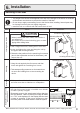
Installation 1. Apply Wall Packing to the rear side of the remote controller. 2. Connect the remote controller wires to the separate remote controller cord. 3. Remove the cover of the remote control, mark the location of the screw holes, and drill holes for the wall anchors. 4. Insert the wall anchors, screw the remote control to the wall and replace the cover.