Portable Air Conditioner 6000/8000/10000 BTU User’s Manual Model NPPAC6KWM / NPPAC8KWM / NPPAC10KWM READ THIS MANUAL CAREFULLY BEFORE USING YOUR PORTABLE AIR CONDITIONER AND KEEP IT FOR FUTURE REFERENCE.
Product Registration Thank you for purchasing a Norpole™ product. The first step to protect your new product is to complete the product registration on our website: www.mcappliance.com/register. The benefits of registering your product include the following: 1. Registering your product will allow us to contact you regarding a safety notification or product update. 2. Registering your product will allow for more efficient warranty service processing when warranty service is required. 3.
CONTENTS PRODUCT REGISTRATION . . . . . . . . . . . . . . . . . . . . . . . . . . . . . . . . . . . . . . . 2 IMPORTANT SAFETY INSTRUCTIONS. . . . . . . . . . . . . . . . . . . . . . . . . . . . . . . 4 SPECIFICATIONS. . . . . . . . . . . . . . . . . . . . . . . . . . . . . . . . . . . . . . . . . . . . . . . 6 PARTS IDENTIFICATION. . . . . . . . . . . . . . . . . . . . . . . . . . . . . . . . . . . . . . . . . . 7 INSTALLATION INSTRUCTIONS. . . . . . . . . . . . . . . . . . . . . . . . . . . . . . . . . .
Important Safety Instructions NOTE: This user manual encompasses information for the nppac6kwm, the nppac8kwm and the nppac10kwm. Make note of the unit you own while reading operation instructions as there may be some discrepancies. Explanation of Symbols WARNING: Hazards or unsafe practices which COULD result in severe personal injury or death. CAUTION: Hazards or unsafe practices which COULD result in minor personal injury or property damage. IMPORTANT SAFETY INSTRUCTIONS 1.
19. Contact customer service or an authorized service technician for repair or maintenance of this unit. DO NOT try to take apart or repair the unit by yourself. 20. Turn off and unplug the unit if strange sounds, smells, or smoke come from it. 21. If the appliance is knocked over during use, turn off the unit and unplug it immediately. Visually inspect the unit to ensure there is no damage.
SPECIFICATIONS Figure 1 H D W Model Dimensions (W x H x D) Weight BTU SACC BTU Voltage NPPAC6KWM NPPAC8KWM NPPAC10KWM 13.0” x 24.2” x 12.5” 13.0” x 24.2” x 12.5” 14” x 27.7” x 13.6” 41.4 lbs. 44.1 lbs. 52.9 lbs. 6000 8000 10000 3000 3800 5500 115V / 60Hz 115V / 60Hz 115V / 60Hz Watts 676 900 1110 Current 6.0A 8.5A 9.8A R410A / 9.52 oz. R410A / 10.58 oz. Refrigerant Type Operating Temperature Range R410A / 7.4 oz.
PARTS IDENTIFICATION Figure 2 a b c d g TIMER ON MODE TEMP h i e SHORT CUT ON/OFF FAN TIMER OFF SLEEP LED FOR NPPAC6KWM k j l f n FOR NPPAC8KWM & NPPAC10KWM m Front Rear a. Control Panel e. Panel j. Drain Outlet b. Remote Signal Receptor f. Caster k. Air Outlet c. Horizontal Louver Control Lever (Fixed or manually adjusted) g. Handle (Both sides) l. Lower Air Intake d. Vertical Louver Control Lever (Fixed or manually adjusted) h. Air Filter (Behind the grille) m.
INSTALLATION INSTRUCTIONS TOOLS NEEDED • Medium Philips screwdriver • Tape measure or ruler • Knife or scissors • Saw (optional, to shorten window adaptor for narrow windows) ACCESSORIES smaller windows.
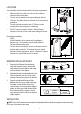
LOCATION Figure 3 Your installation location should meet the following requirements: • Make sure that you install your unit on a level surface to minimize noise and vibration. • The unit must be installed near a grounded plug, and the Collection Tray Drain (found on the back of the unit) must be accessible. • The unit should be located at least 12” (30cm) from the nearest wall to ensure proper air conditioning.
Type 1: Hung Window Installation Foam seal B (Adhesive type-shorter) 1 Foam seal A (Adhesive type) Cut the adhesive foam seal A and B strips to the proper lengths, and attach them to the window sash and frame as shown. Window Slider B (if required) Insert the window slider assembly into the window opening. Window Slider A 2 Foam seal C (Non-adhesive type) Cut the non-adhesive foam seal C strip to match the width of the window.
Insert the window slider adaptor into the hole of the window slider. 5 Type 2: Sliding Window Installation Foam seal B (Adhesive type-shorter) Cut the adhesive foam seal A and B strips to the proper lengths, and attach them to the window sash and frame as shown. 1 Foam seal A (Adhesive type) Window Slider B (if required) 2 Window Slider A Insert the window slider assembly into the window opening. Foam seal C (Non-adhesive type) Cut the non-adhesive foam seal C strip to match the window height.
Security Bracket If desired, install the security bracket with 2 screws as shown. 4 2 Screws Insert the window slider adaptor into the hole of the window slider. 5 NOTE: To ensure proper function, DO NOT overextend or bend the hose. Make sure that the air outlet of the exhaust hose has a clearance of about 20 in. (48cm). These illustrations are for explanation only, your air conditioner may be slightly different.
REMOTE CONTROL (FOR NPPAC6KWM) Before you begin using your new air conditioner, make sure to familiarize yourself with the remote control. The following is a brief introduction to the remote control itself. For instructions on how to operate your air conditioner, refer to the OPERATING INSTRUCTIONS section of this manual. For best results, make sure you are pointing the remote control at the air conditioner.
g. Temperature/Timer Display: Displays the set temperature by default, or timer setting when using TIMER ON/OFF functions. • Temperature range: 62°F-86°F (17°-30°C) • Timer setting range: 0-24 hours This display is blank when operating in FAN mode. h. Fan Speed Display: Shows set fan speed of HIGH “>>>>>>>>>>”, MEDIUM “>>>>>>>”, or LOW “>>>”. Not all models have medium speed. This display is blank when set to AUTO speed.
REMOTE CONTROL (For NPPAC8KWM & NPPAC10KWM) Before you begin using your new air conditioner, make sure to familiarize yourself with the remote control. The following is a brief introduction to the remote control itself. For instructions on how to operate your air conditioner, refer to the OPERATING INSTRUCTIONS section of this manual. For best results, make sure you are pointing the remote control at the air conditioner.
f. Temperature Display – Shows temp setting. Off when unit is in FAN Mode. g. Lock Display – Lit when the remote control is locked. h. Fan Speed Display – Shows set fan speed of AUTO, low, medium, or high. Not all models have medium speed. Displays AUTO in DRY mode. INSERTING AND REPLACING BATTERIES Your remote control uses two AAA batteries. To install or replace batteries: 1. Slide the cover on the back of the remote downward, exposing the battery compartment. 2.
OPERATING INSTRUCTIONS CONTROLS Figure 12 b a a. c d Mode Button: Selects the operating mode. Each time you press the button, a mode will change from COOL> FAN>DRY. The mode indicator light indicates what mode is set. NOTE: The unit operates the fan speed automatically. You can only set the fan speed with the remote controller in COOL and FAN modes. b. Down (-) and Up (+) Buttons: Used to adjust the temperature settings in 1° (F or C) increments in a range of 62°F/17°C to 86°F/30°C.
Dry Mode • Press the “MODE” button on the unit or the remote until the “DRY” indicator lights. • The temperature and fan speed cannot be adjusted in this mode. The fan will operate at Low speed. • Keep windows and doors closed and do not run the exhaust duct to window. Auto Mode (Remote Control Only) • Press the “MODE” button until the “AUTO” indicator lights. • Press the Temp Up or Down on remote select your desired room temperature.
2. Press TEMP/TIME adjust button to set time. Push “UP” or “DOWN” to change the time forward or backward. 3. Each time you press the button, the time moves forward or backward by one minute. Hold the button to change the time in 10 minutes increments. 4. When the correct time is set, push and release the CLOCK button, or wait for 5 seconds until the time stops flashing. NOTE: The time of the CLOCK must be set before the AUTO-TIMER feature will operate. NOTE: Clock accuracy is within 15 seconds per day.
CARE AND MAINTENANCE WARNING: Turn the unit off and remove the plug from the wall outlet before maintenance or cleaning. WARNING: DO NOT use flammable liquids or chemicals to clean the unit. • DO NOT immerse in or spray with water to clean. • DO NOT operate the unit if the power cord is damaged. • The water bucket should be cleaned every few weeks or as needed. DO NOT leave water in the bucket when unit is not being used. ALWAYS empty before storage or as soon as “P1” is displayed.
TROUBLESHOOTING Please check the following before calling for service. Problem Possible Cause Troubleshooting Unit does not turn on when pressing ON/OFF button. P1 Error Code The Water Collection Tray is full. Turn off and unplug the unit, drain the water from the Water Collection Tray and restart the unit. In COOL mode: Room temperature is lower than the set temperature. Reset the temperature. The air filter is blocked or dirty. Turn off the unit and clean the filter according to instructions.
LIMITED WARRANTY Norpole, Inc. warrants each new PORTABLE AIR CONDITIONER to be free from defects in material and workmanship and agrees to remedy any such defect or to furnish a new part(s) (at the company’s option) for any part(s) of the unit that has failed during the warranty period. Parts and labor expenses are covered on this unit for a period of one year from the date of purchase. In addition, Norpole, Inc.
Aire acondicionado portátil 6000/8000/10000 BTU Manual del usuario Modelo NPPAC6KWM / NPPAC8KWM / NPPAC10KWM LEA ATENTAMENTE ESTE MANUAL ANTES DE USAR EL AIRE ACONDICIONADO PORTÁTIL Y CONSÉRVELO PARA CONSULTARLO EN EL FUTURO.
REGISTRO DEL PRODUCTO Una vez más, le agradecemos por comprar un producto Norpole™. El primer paso para proteger su producto nuevo es registrarlo en nuestro sitio web: www.mcappliance.com/register. Algunos de los beneficios de registrar el producto son los siguientes: 1. Si registra el producto, podremos informarle sobre notificaciones de seguridad o actualizaciones del producto. 2. Cuando requiera utilizar el servicio de la garantía, podrá disfrutar de un procesamiento más eficiente. 3.
CONTENIDO REGISTRO DEL PRODUCTO . . . . . . . . . . . . . . . . . . . . . . . . . . . . . . . . . . . . . 2 INSTRUCCIONES DE SEGURIDAD IMPORTANTES . . . . . . . . . . . . . . . . . . . 4 ESPECIFICACIONES . . . . . . . . . . . . . . . . . . . . . . . . . . . . . . . . . . . . . . . . . . . . 6 IDENTIFICACIÓN DE PIEZAS . . . . . . . . . . . . . . . . . . . . . . . . . . . . . . .
INSTRUCCIONES DE SEGURIDAD IMPORTANTES NOTA: Este Manual del usuario incluye información para el NPPAC6KWM, el NPPAC8KWM y el NPPAC10KWM. Mientras lee las instrucciones de operación, tome notas acerca de su unidad, ya que podría haber diferencias. EXPLICACIÓN DE LOS SÍMBOLOS ADVERTENCIA: Tenga cuidado con los peligros o las prácticas poco seguras que PODRÍAN provocar lesiones graves o la muerte.
19. 20. 21. 22. 23. 24. Para la reparación o el mantenimiento de esta unidad, comuníquese con un técnico de servicio autorizado o con el servicio de atención al cliente. NO intente reparar o desarmar la unidad usted mismo. Apague y desenchufe la unidad si de ella sale humo o sonidos u olores extraños. Si, durante el uso, la unidad se cae, apáguela y desenchúfela de inmediato. Inspeccione la unidad visualmente para asegurarse de que no presente daños.
ESPECIFICACIONES Figura 1 H D W Modelo NPPAC6KWM NPPAC8KWM NPPAC10KWM 13.0” x 24.2” x 12.5” 13.0” x 24.2” x 12.5” 14” x 27.7” x 13.6” Peso 41,4 lbs. 44,1 lbs. 52,9 lbs. BTU 6000 8000 10000 Dimensiones (W x H x D) SACC BTU Voltaje 3000 3800 5500 115V / 60Hz 115V / 60Hz 115V / 60Hz Vatios 676 900 1110 Corriente 6,0A 8,5A 9,8A R410A / 9.52 oz. R410A / 10.58 oz. Tipo de refrigerante Rango de temperatura ambiente de operación R410A / 7.4 oz.
IDENTIFICACIÓN DE PIEZAS Figura 2 a b c d g TEMP k j f c. d. TIMER OFF SLEEP LED n PARA NPPAC8KWM Y NPPAC10KWM m Parte delantera Panel de control Receptor de señal del control remoto Manija de control del deflector horizontal (fija o de ajuste manual) Manija de control del deflector vertical (fija o de ajuste manual) FAN PARA NPPAC6KWM l a. b. TIMER ON MODE h i e SHORT CUT ON/OFF Parte posterior e. f. g. h. i.
INSTRUCCIONES DE INSTALACIÓN HERRAMIENTAS NECESARIAS • • • • Destornillador Philips mediano Cinta o regla para medir Cuchillo o tijera Sierra (opcional, para acortar el adaptador para las ventanas en el caso de ventanas angostas) ACCESORIOS El kit para la instalación de la unidad en una ventana es para ventanas colgantes o deslizantes de 26,5 a 48" (67,5 a 123 cm) y puede acortarse para ventanas más pequeñas.
UBICACIÓN Figura 3 La ubicación de instalación debe cumplir estos requisitos: • • • • Asegúrese de instalar la unidad en una superficie nivelada para minimizar los ruidos y las vibraciones. La unidad debe instalarse cerca de un enchufe con conexión a tierra y debe ser posible acceder a la descarga de la bandeja de recolección (que se encuentra en la parte posterior de la unidad).
Tipo 1: Instalación en una ventana colgante Sello de espuma B (adhesivo, más corto) 1 Sello de espuma A (adhesivo) Corte las tiras de sellos de espuma adhesivos A y B de un largo adecuado, y colóquelas en el marco y en las hojas de la ventana, como se muestra. Deslizador para la ventana B (si se requiere) Inserte el conjunto del deslizador para la ventana en el abertura de la ventana.
Inserte el adaptador del deslizador para la ventana en el orificio dispuesto para tal fin. 5 Tipo 2: Instalación en una ventana deslizante Sello de espuma B (adhesivo, más corto) Corte las tiras de sellos de espuma adhesivos A y B de un largo adecuado, y colóquelas en el marco y en las hojas de la ventana, como se muestra. 1 Sello de espuma A (adhesivo) Deslizador para la ventana B (si se requiere) 2 Inserte el conjunto del deslizador para la ventana en el abertura de la ventana.
Si lo desea, instale el soporte de seguridad con dos tornillos, tal como se muestra. Soporte de seguridad 4 2 tornillos Inserte el adaptador del deslizador para la ventana en el orificio dispuesto para tal fin. 5 NOTA: Para asegurar un funcionamiento correcto, NO extienda demasiado la manguera ni la doble. Asegúrese de que la salida de aire de la manguera de escape tenga un espacio libre aproximado de 20 pulg. (48 cm).
CONTROL REMOTO (PARA NPPAC6KWM) Antes de comenzar a utilizar el nuevo aire acondicionado, asegúrese de familiarizarse con el control remoto . A continuación se proporciona una breve introducción sobre el control remoto . Para obtener instrucciones acerca de cómo utilizar el aire acondicionado, consulte la sección INSTRUCCIONES DE OPERACIÓN de este manual . Para obtener mejores resultados, apunte el control remoto hacia el aire acondicionado .
INDICADOR DEL CONTROL REMOTO 1 . Indicador de transmisión: Se enciende cuando el control remoto está transmitiendo . 2 . Indicador de modo: Muestra el modo de funcionamiento actual . AUTO – COOL – DRY – FAN a c d Figura 9 e b f g 3 . ON/OFF Display: Muestra el estado de la unidad de A/C . 4 . Timer-On/Off: Muestra si el TIMER ON / TIMER OFF está activado . 5 . Indicador de batería: Batería baja . 6 . Indicador de reposo: Indica si el modo Sleep está activado o desactivado . 7 .
CONTROL REMOTO (PARA NPPAC8KWM Y NPPAC10KWM) Antes de comenzar a utilizar el nuevo aire acondicionado, asegúrese de familiarizarse con el control remoto . A continuación se proporciona una breve introducción sobre el control remoto . Para obtener instrucciones acerca de cómo utilizar el aire acondicionado, consulte la sección INSTRUCCIONES DE OPERACIÓN de este manual . Para obtener mejores resultados, apunte el control remoto hacia el aire acondicionado .
e . Indicador de reposo: indica si el modo Sleep está activado o desactivado . f . Indicador de temperatura: muestra la temperatura seleccionada . Se apaga cuando la unidad está en el modo FAN . g . Indicador de bloqueo: se enciende cuando el control remoto está bloqueado . h. Indicador de velocidad del ventilador: muestra la velocidad del ventilador configurada en AUTO, Low, Medium o High . No todos los modos cuentan con una velocidad media . En el modo Dry, se indica la velocidad AUTO .
INSTRUCCIONES DE OPERACIÓN CONTROLES Figura 12 b Cool MODE Fan Dry a a. c d Botón Mode: permite seleccionar el modo de operación. Cada vez que presione este botón, el modo cambiará de COOL>FAN >DRY. La luz indica el modo que está seleccionado. NOTA: La unidad selecciona la velocidad del ventilador automáticamente. Solo es posible configurarla cuando el control remoto está en los modos COOL y FAN. b.
Modo Dry • Presione el botón "MODE" en la unidad o en el control remoto hasta que se encienda el indicador "DRY". • No es posible modificar la temperatura ni la velocidad del ventilador en este modo. El ventilador funcionará a baja velocidad. • Mantenga las puertas y ventanas cerradas, y no extienda el conducto de escape hacia una ventana. Modo Auto (solo con control remoto) • Presione el botón MODE hasta que se encienda el indicador AUTO.
2. Presione el botón de ajuste TEMP/TIME para establecer la hora. Presione los botones "UP" o "DOWN" para adelantar o retrasar la hora. 3. Cada vez que presione el botón, la hora se adelantará o se retrasará un minuto. Manténgalo presionado para cambiar la hora en incrementos de 10 minutos. 4. Una vez establecida la hora correcta, presione y suelte el botón CLOCK o espere cinco segundos hasta que el indicador de hora deje de parpadear.
CUIDADO Y MANTENIMIENTO ADVERTENCIA: Apague la unidad y desconecte el enchufe de la pared antes de realizar tareas de mantenimiento o limpieza. ADVERTENCIA: NO utilice líquidos ni químicos inflamables para limpiar la unidad. • NO sumerja ni rocíe con agua la unidad para limpiarla. • NO opere la unidad si el cable de alimentación está dañado. • La cubeta de agua debe limpiarse cada dos semanas o según se necesite. NO deje agua en la cubeta cuando la unidad no vaya a usarse.
RESOLUCIÓN DE PROBLEMAS Revise lo siguiente antes de llamar al servicio técnico. Problema Causa posible Resolución de problemas La unidad no se Código de error P1. enciende al presionar el botón ON/OFF. En modo COOL: la temperatura ambiente es inferior a la temperatura establecida. La unidad no refrigera correctamente. La unidad hace ruido y vibra demasiado. La unidad hace ruido de gorgoteo. La bandeja de recolección de agua está llena.
GARANTÍA LIMITADA Norpole, Inc . garantiza que cada AIRE ACONDICIONADO PORTÁTIL nuevo no tendrá defectos de materiales ni de fabricación y acepta reparar un defecto de este tipo, si lo hubiera, o reponer piezas nuevas de la unidad (a elección de la empresa) en caso de que fallen durante el período de garantía . Los gastos por piezas y mano de obra en esta unidad están cubiertos por un período de un año a partir de la fecha de compra . Asimismo, Norpole, Inc .