
s Manual
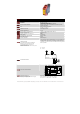

DEVICE SAFE M / SAFE M.1
Mat and contact edges control relay with a max. mats-resistance
APPLICATIONS
of 200 ohms
APPROVALS
CE, TÜV, UL, C-UL
CONTACTS
3 normally open safety, 1 normally auxiliary closed
LED indicators for status and supply diagnostic
SPECIAL CHARACTERISTICS
Opposite polarity between chanels
With (SAFE M) and without (SAFE M.1) automatic start
LED
Power, channel 1 and channel 2
OPERATING VOLTAGE
24 V AC / DC (electronic fuse)
SAFE M: 115 V AC (with galvanic disconnection/transformer)
POWER CONSUMPTION
24, 115 V AC: ca. 5 VA, 24 V DC: 3 W
START UP DELAY / FALLBACK TIME
< 50 ms / < 30 ms (24 V AC < 50 ms)
CONTACT CAPACITY max.
5 A, 240 V AC, 24 V DC
CONTACT CAPACITY min. at 24V DC (*)
6 mA
SIMULTANEITY
ENVIRONMENTAL TEMPERATURE
-25°C to + 55°C
SWITCHING CAPACITY
1200 VA (resistive load)
CONTACT SECURITY
6,3 A quick acting (normally open) or 4 A time lag (normally closed)
OPERATING MODE
(*) We offer all devices who have a CONTACT
CAPACITY of min. 100 mA at 24 V DC with
hard gold-plated contacts. In this way the
CONTACT CAPACITY of min. 100 mA is only 4 mA.
Please ask our sales team!
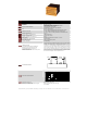
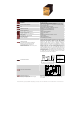
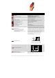
CONNECTION DIAGRAM
A supply voltage must be applied to terminals A1 and A2. Power LED
illuminates and 24V DC is available at terminal S11. Terminals S12 and S22
must be connected according to the application example selected to meet
the application requirements. To start the unit terminals S33 and S34 must
be bridged with a normally open contact. The unit works if you close this
contact. At this time the contacts 13-14, or bridge for automatically start 23-
24 and 33-34 are closed. The LEDs channel 1 and channel 2 illuminate. In
series to this start button an external contactor can be controlled.
For automatic start (SAFE M only) the terminals S33 and S34 must be
brigded. The safety mats and safety bars must be of 4 wire technology or 2
wire technology and have to agree to the cross circuit principle.
For version with detachable clamps (screw - or cage clamps) ...
please ask our sales team!
S33
S11 S21
S12S34
Start
S22
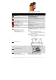
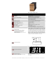
FUNCTION CIRCUIT DIAGRAM
S12
Überwachungslogik /
monitoring logic
~ ~
~
~
+
=
K1
elektr. Sicherung
electr. fuse
Transformator
transformer
A1
(+)
A2
(-)
S34
S33 S11
14
K2
K2
3424 42
13
K1
S22S21
3323 41
Certifications according to
Safety relevant substance data
Depending on wiring (only max. values are given)
EN ISO 13849-1: PLe, Cat. 3
MTTFd: 73,21 years / high, DC: 90% / medium, CCF: achieved
PFH: 5,81*10
-9 1
/
h
, SFF: 99%
NORSTAT INC. 300 Roundhill Dr. Rockaway, NJ 07866 Tel: 973-586-2500 Fax: 973-586-1590 www.norstat.com