
s Manual
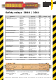


Emergency stop and safety gate monitoring relays
DEVICE
SAFE 5 / SAFE 5.1
Emergency stop
APPLICATIONS
and safety gate monitoring relay
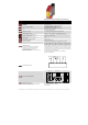
APPROVALS
CE, TÜV, UL, C-UL
CONTACTS
2 normally open safety
LED indicators for status and supply diagnostic
SPECIAL CHARACTERISTICS
With (SAFE 5) and without (SAFE 5.1) start control
LED
Power, channel 1 and channel 2
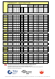
OPERATING VOLTAGE
24 V AC / DC (electronic fuse)
POWER CONSUMPTION
ca. 1,6 VA / 1,6 W
START UP DELAY / FALLBACK TIME
< 50 ms / < 80 ms (AC) , < 50 ms (DC)
CONTACT CAPACITY max.
6 A, 250 V AC, 24 V DC
CONTACT CAPACITY min. at 24V DC (*)
6 mA
SIMULTANEITY
ENVIRONMENTAL TEMPERATURE
-25°C to + 55°C
SWITCHING CAPACITY
1500 VA
(resistive load)
CONTACT SECURITY
6,3 A quick acting or 4 A time lag
OPERATING MODE
(*) We offer all devices who have a CONTACT
CAPACITY of min. 100 mA at 24 V DC with
hard gold-plated contacts. In this way the
CONTACT CAPACITY of min. 100 mA is only 4 mA.
Please ask our sales team!
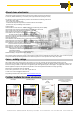
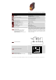
CONNECTION DIAGRAM
A supply voltage must be applied via emergency stop to terminals A1 and
A2. Power LED illuminates if the emergency stop is closed. To start the unit
terminals Y2 and Y1 must be bridged with a normally open contact. The unit
works if you close this contact. At this time the contacts 13-14, 23-24 are
closed. The LEDs channel 1 and channel 2 illuminate. In series to this start
button an external contactor can be controlled.
For version with detachable clamps (screw - or cage clamps) ...
please ask our sales team!
A1 Y1 Y2
A2
+24V 0V
Start
FUNCTION CIRCUIT DIAGRAM
-
AC
A1
K1
K2DC
+
14 24
controll-
logic
A2
electronic
fuse
Y2 13 23Y1
Certifications according to
Safety relevant substance data
Depending on wiring (only max. values are given)
EN ISO 13849-1: PLe, Cat. 3 (***see product-navigator page 4)
MTTFd: 71 years / high, DC: 90% / medium
CCF: achieved
Not-Halt
E-Sto
p
NORSTAT INC. 300 Roundhill Dr. Rockaway, NJ 07866 Tel: 973-586-2500 Fax: 973-586-1590 www.norstat.com