GS Series GSTC/GSP Indoor GSTC Outdoor Engineering Manual 1503540-C
PROPRIETARY NOTICE This document and the information disclosed herein are proprietary data of WALTER MEIER LTD. Neither this document nor the information contained herein shall be reproduced used, or disclosed to others without the written authorization of WALTER MEIER LTD., except to the extent required for installation or maintenance of recipient’s equipment. All references to the NORTEC name should be taken as referring to WALTER MEIER LTD.
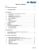
TABLE OF CONTENTS Subject Page 10-00 PRINCIPLE OF OPERATION 1. PRINCIPLE OF OPERATION . . . . . . . . . . . . . . . . . . . . . . . . . . . . . . . . . . . . . . . . . . . . . . . . . . . . . 2 A. COMBUSTION SYSTEM . . . . . . . . . . . . . . . . . . . . . . . . . . . . . . . . . . . . . . . . . . . . . . . . . . . . . . . . . . . . . 2 10-10 OPERATION 1. WATER MANAGEMENT - BETTER EFFICIENCY THAN EVER . . . . . . . . . . . . . . . . . . . . . . . . . . 8 A. B. C. D. E. F. G. 2. INTRODUCTION . . . .
K. L. M. N. O. P. Q. ON-LINE . . . . . . . . . . . . . . . . . . . . . . . . . . . . . . . . . . . . . . . . . . . . . . . . . . . . . . . . . . . . . . . . . . . . . . . . .24 LINKS 2 . . . . . . . . . . . . . . . . . . . . . . . . . . . . . . . . . . . . . . . . . . . . . . . . . . . . . . . . . . . . . . . . . . . . . . . . . .24 OUTDOOR 120 VAC . . . . . . . . . . . . . . . . . . . . . . . . . . . . . . . . . . . . . . . . . . . . . . . . . . . . . . . . . . . . . . . .26 DRAIN WATER SUMP PUMP . . . .
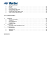
LIST OF FIGURES Figure Page 10-00 PRINCIPLE OF OPERATION Figure 1. Figure 2. Figure 3. Figure 4. GS Indoor Series. . . . . . . . . . . . . . . . . . . . . . . . . . . . . . . . . . . . . . . . . . . . . . . . . . 3 GS Outdoor Series . . . . . . . . . . . . . . . . . . . . . . . . . . . . . . . . . . . . . . . . . . . . . . . . 3 GSTC Key Pad . . . . . . . . . . . . . . . . . . . . . . . . . . . . . . . . . . . . . . . . . . . . . . . . . . . 4 GSP Key Pad . . . . . . . . . . . . . . . . . . . . . . . . .
LIST OF TABLES Table Page 10-00 PRINCIPLE OF OPERATION Table 1. Table 2. 2008-10-01 Technical Data . . . . . . . . . . . . . . . . . . . . . . . . . . . . . . . . . . . . . . . . . . . . . . . . . . . 2 Standard Features . . . . . . . . . . . . . . . . . . . . . . . . . . . . . . . . . . . . . . . . . . . . . . . .
THIS PAGE INTENTIONALLY LEFT BLANK 2008-10-01
10-00 PRINCIPLE OF OPERATION 10-00 Page 1 2008-10-01
1. PRINCIPLE OF OPERATION A. Combustion System (1) The combustion system is based on a fully modulating forced draft combustion air blower, a negative pressure regulated gas valve, and a 100% premix burner. On a call for humidity, the combustion air blower starts and creates a negative pressure across an orifice located at the air inlet. (2) The blower is energized to purge the system, then the hot surface igniter is activated.
Figure 1. GS Indoor Series Figure 2.
Figure 3. GSTC Key Pad Figure 4.
Table 2.
THIS PAGE INTENTIONALLY LEFT BLANK 10-00 Page 6 2008-10-01
10-10 OPERATION 10-10 Page 7 2008-10-01
1. WATER MANAGEMENT – BETTER EFFICIENCY THAN EVER A. Introduction (1) The GS Series of humidifiers is equipped with a unique float chamber water level monitoring device. Two magnetic floats (one is a backup) measure 5 different water levels in the humidifier for proper operation. The float chamber and board are located away from the boiling action to increase reading accuracy and reduce mineral buildup since it is not in the boiling water.
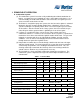
Model GSTC 100 GSTC 200 GSTC 300 GSTC 400 GSTC 500 GSTC 600 A B C D Vent Dia B Type Vent Dia BH Type Shipped Weight Operating Weight in cm in cm in cm in cm in cm in cm lbs kg lbs kg 20.8 52.8 6.3 16 9.3 23.6 16.1 40.8 4 10.2 3 7.6 267 121 423 192 27.2 69 11.6 29.5 14.6 37.1 22.4 56.8 5 12.7 4 10.2 355 161 599 272 42.7 109 10.9 27.8 14.6 37.1 38 96.4 7 17.8 5 12.7 485 220 970 440 42.7 109 10.9 27.8 14.6 37.1 38 96.4 7 17.
Figure 3.
B. Safety Water Level Control Check (1) To ensure safe operation, the humidifier constantly monitors the back up float of the humidifier and also performs float checks at regular intervals. C. Self Diagnostic (1) This feature allows the user to activate various hardware elements within the system to prove operational compliance. D.
(3) All control electronics are integral to humidifier cabinet and do not require separate cabinet on the humidifier. B. Remote Fault Indication (1) The GS Series provides output signals of the following type: (a) Humidifier “ON” (b) Humidifier “Active” (c) Humidifier “Service” (d) Humidifier “Fault” C.
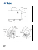
through the roof without any special requirements when using BH venting. Required vent flue size depends on unit model. All connections to the flue pipes are made without having to open the humidifier cabinetry. (3) The GS Outdoor Series comes complete with BH vent, ready for easy assembly. 5. CLEARANCES (1) The clearance dimensions shown in Figure 4 and 5 are for reference only and are the minimum requirements for maintenance of the humidifier. (2) All units have frontal cleaning port access.
Figure 4. GSTC/GSP Indoor Clearance Figure 5.
6. STEAM INSTALLATION GUIDELINES (1) The GS Series humidifier comes with a single steam outlet on all capacities. The GS 100, 200/300, 400/500/600 have respectively (1.75” (4.4 cm) O.D., 3” (7.6 cm) O.D. and 4” (10.16) O.D.). Consult option and accessories section for more details. Refer to the Steam Absorption and Distribution Manual, Form #XX-231 for design of the steam distribution system. 7. CALCULATION OF ANNUAL OPERATING COSTS A.
THIS PAGE INTENTIONALLY LEFT BLANK 10-10 Page 16 2008-10-01
10-20 MAINTENANCE 10-20 Page 17 2008-10-01
1. WATER CONDITIONS VS. HUMIDIFIER CLEANING REQUIREMENTS (1) The GS Series humidifiers are to operate on cold potable, De-Ionized (DI) or Reverse-Osmosis (RO) water supply and since the output of all GS Series humidifiers is pure clean steam, minerals from the incoming water are left behind. These minerals will eventually coat the tank walls or settle to the bottom of the tank.
maintenance a step further than RO and all the GS Series components are ready for RO or DI water use as a standard. (10) Contact your local Nortec representative for a quotation of a water treatment system suited for your application. 2. PREVENTIVE MAINTENANCE (1) The installation manuals of the GS Series of Gas Steam humidifier come with a complete Maintenance chart in order to guide internal personnel in cleaning and monitoring activities.
THIS PAGE INTENTIONALLY LEFT BLANK 10-20 Page 20 2008-10-01
10-30 OPTIONS & ACCESSORIES 10-30 Page 21 2008-10-01
1. OPTIONS AND ACCESSORIES AVAILABLE A. Nortec Modulating Humidistat with Digital Display (1) NORTEC humidistats for GSTC or GSP Gas Steam humidifiers feature proportional + integral control with setpoint range of 10-95% RH. The humidistat connects directly to the low voltage terminal strip via 3 wires (shielded if run exceeds 10 m). The humidistat accurately controls RH in a zone or space.
D. Nortec On / Off Controls with Digital Display (1) 252-0273 - Duct Mounted Safety High Limit On/Off Humidistat (if used) is wired to make on drop in humidity, break on rise to safety setpoint. It should be set to approximately 85% RH as a safety to prevent saturation and wetting in the duct. (2) 132-9203 - A Duct Mounted Safety Air-Proving On/Off Switch (if used) is wired to make on airflow, break on no flow. It is used as a safety to prevent saturation when no air is flowing through the duct.
I. Indoor Freeze Protection (1) 150-7058 - GSTC Indoor Freeze protection package provides the unit configured with keep warm feature, remote fault indication and a normally open drain valve to protect if freezing conditions may occur. The keep warm feature will ensure the water temperature is kept between 140ºF (60ºC) and 160ºF (71ºC).
(3) b) 252-7111 - BACnet MSTP c) 252-7113 – Johnson N2 d) 252-7113 – LonWorks Features a) Digital Feedback for unit standby/humidifying mode. b) Digital feedback for service required. c) Digital feedback for fault indication. d) System demand display. e) Control room setpoint. f) Control high limit setpoint. g) Control room %RH. h) Control high limit %RH. i) Control enable/disable. j) Networking capabilities of linking 8 units to one Nortec controller. Figure 1.
M. DRAIN WATER SUMP PUMP (1) Externally mounted below humidifier. For use when no floor drain is available and water must be pumped higher than the bottom of the humidifier (special high temperature model). Rated for use with all GS models. Recommended model: W.W. Grainger #4RD29 or #4RD32. N. STEAM DISTRIBUTION (1) Used in ducts or air handling units, available in stainless steel. (2) Steam is dispersed through evenly spaced outlet orifices and upward perpendicular to the airflow.
Figure 3. Steam Distributor Figure 5. Short Absorption Manifold 10-30 Page 27 2008-10-01 Figure 4.
THIS PAGE INTENTIONALLY LEFT BLANK 10-30 Page 28 2008-10-01
10-40 SPECIFICATION 10-40 Page 29 2008-10-01
1. GENERAL A. General (1) NORTEC GS Series Gas-Fired Humidifier[s] as indicated on drawing[s] and as indicated on schedule[s]. (2) Complete and operable humidification system [which meets applicable building codes]. (3) Equipment start-up and project inspection by qualified factory trained representative. B. Quality Assurance (1) Manufacturer: For each product specified, provide components by same manufacturer throughout.
(6) Submit minimum water quality requirements and water pressure requirements. D. Extra Materials (1) Furnish extra materials described below that match products installed and that are packaged with protective covering for storage and identified with labels describing contents. E. References (1) ANSI/NFPA 70 - National Electrical Code. F. Coordination (1) Coordinate location and installation of humidifiers in ducts and air-handling units.
(4) (f) Provide easily accessible, primary voltage terminal block, internal to cabinetry, for single point field connection of electrical supply. (g) Single point connection for gas inlet must be provided. Internal piping from gas inlet to burners must be factory installed and tested. Field piping from the gas inlet to the burners is not allowed. (h) Humidifier to prevent “back-siphoning” using an internal air gap for supply water, to meet local plumbing codes.
(6) 10-40 Page 33 2008-10-01 (e) Blower speed rotation must to be monitored to ensure proper control of input modulation. System will lock out gas valve operation if proper blower speed is not detected. (f) A secondary combustion air safety, in addition to blower speed monitoring, utilizing a mechanical pressure differential switch, must be used with each blower to ensure combustion air is entering the pre-mix blower properly.
(7) Factory mounted, full size, backlit, Liquid Crystal Display provides full operational status. Display to include a keypad for user interface and adjustment of operational parameters including: (a) Unit output (lbs/hr or kg/hr) 25 lbs/hr to full output. (b) Water level in the tank. (c) Modulating control demand status. (d) On/off control and safety (High limit, air proving) circuit status. (e) Actual room and/or duct RH, and humidity set point, when using transducer input(s).
3. EXAMINATION A. Examination (1) Examine ducts, air-handling units, and conditions for compliance with requirements for installation tolerances and other conditions affecting performance. (2) Examine roughing-in for piping systems to verify actual locations of piping connections before humidifier installation. (3) Proceed with installation only after unsatisfactory conditions have been corrected. B. Installation (1) Install humidifiers and steam dispersion panels per manufacturers’ instructions.
D. Training (1) Training of the Owner’s operation and maintenance personnel is required in cooperation with the Commissioning Authority. Provide competent, factory authorized personnel to provide instruction to operation and maintenance personnel concerning the location, operation, and troubleshooting of the installed systems. The instruction shall be scheduled in coordination with the Commissioning Authority after submission and approval of formal training plans.
THIS PAGE INTENTIONALLY LEFT BLANK 10-40 Page 37 2008-10-01
WARRANTY (1) WALTER MEIER INC. and/or WALTER MEIER LTD. (hereinafter collectively referred to as THE COMPANY), warrant for a period of two years after installation or 30 months from manufacturer’s ship date, whichever date is earlier, that THE COMPANY’s manufactured and assembled products, not otherwise expressly warranted (with the exception of the cylinder), are free from defects in material and workmanship.
U.S.A. Walter Meier (Climate USA) Inc. CANADA Walter Meier (Climate Canada) Ltd. 826 Proctor Avenue Ogdensburg, NY 13669 TEL: 1-866-NORTEC-1 EMAIL: northamerica.climate@waltermeier.com WEBSITE: www.humidity.