
User Manual


2
SENSITIVITY TEST
1. Press and hold the TEST/SILENCE button for 4 seconds. Once the test
starts, the smoke alarm LED fl ashes 1 to 9 times.
2. Count the number of LED fl ashes and use the following table to determine
if any action is necessary.
FLASHES INDICATION ACTION
0-1
Unserviceable
hardware fault
Reset and rerun sensitivity test. If
the error persists, replace the unit.
2-3
Unit is becoming
insensitive
Clean and reset the unit. Rerun
sensitivity test. If the error persists,
replace the unit.
4-7
Unit is within normal
sensitivity range
No action required
8-9
Unit is becoming too
sensitive
Verify that the optical chamber is
snapped down securely. Clean
the unit and replace the optical
chamber.
After the LED fl ashes, if the sensitivity is within limits and all other tests pass,
the unit goes into alarm and resets after 7 seconds. If the sensitivity is not
within limits, or an unserviceable hardware fault has been detected, the unit
LED extinguishes until the unit is serviced.
LED FUNCTIONS
Flashing — Flashes every 9 seconds to indicate normal operation.
On — Detects smoke
Off — Trouble or maintenance is required.
WHEN TO REPLACE THE BATTERIES
When the batteries are low, the unit extinguishes its LED and chirps every 45
seconds until the batteries are replaced. The low battery trouble chirps can be
silenced for 24 hours by pressing the TEST/SILENCE button. Battery life is a
minimum of one year, and varies depending on how often the unit is tested.
REPLACING THE BATTERIES
Use only 3V lithium batteries listed on the battery compartment cover.
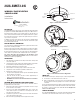
1. Remove the unit from the mounting base, grasp the unit and turn it
counterclockwise approximately 15 degrees.
2. Slide the battery compartment cover away from the smoke alarm to
unsnap it and lift it off. See Figure 2.
3. Remove the batteries and dispose of them properly.
4. Observing correct polarity, insert two new 3V lithium batteries into the
battery compartment and replace the cover.
5. Reattach the unit to the mounting base. See Installation, Step 6.
6. Test the system.
CLEANING
Clean the cover with a dry or damp (water) cloth as needed to keep it free
from dust and dirt.
When necessary, clean the interior and replace the optical chamber (part
number ??????) as follows:
1. To remove the unit from the mounting base, grasp the unit and turn it
counterclockwise approximately 15 degrees.
2. Remove the batteries.
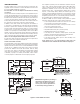
3. Slide a fl at-blade screwdriver in the slot on the alarm cap and gently push
the handle down to pry the alarm cap up and off. See Figure 4.
4. Squeeze the optical chamber where indicated and pull it up and away
from the optical base and discard. See Figure 5.
5. Blow out or use a soft-bristled brush to remove all dust and dirt from the
optical base.
6. Line the new smoke chamber up with the optical base by lining up the
arrows on the optical chamber to the latches on the optical base. Ensure
that the LED cavity in the optical chamber is above the LED and snap the
optical chamber down into place.
7. To replace the alarm cap as follows:
• Line the alarm cap up with the unit.
• Insert the alarm cap into the unit and turn clockwise approximately 15
degrees. It should snap fi rmly into place.
8. Observing proper polarity, replace the batteries and the battery
compartment cover.
9. Reattach the unit to its mounting base. See Installation, Step 6.
10. Test the unit sensitivity.
MAINTENANCE
The units are designed for easy fi eld service and maintenance. When installed
and used properly, they require minimal maintenance.
The unit should be tested weekly.
When a unit requires maintenance, it extinguishes its LED and stops sending
supervisory signals to the alarm Control Panel.
If the Control Panel indicates supervisory trouble for the smoke alarm, perform
the sensitivity test and follow the recommended actions.
SPECIFICATIONS
Voltage 3VDC
Typical average standby current 35µA
Typical test current 2mA
Typical alarm current 70mA
Battery type 3V lithium, Duracell
®
123, Panasonic
®
CR123A, Sanyo
®
123A
Low battery threshold 2.70V causes low battery signal
Sounder 85dBa at 10’ temporal pattern
Low battery beep rate 1 every 45 sec.
Sensitivity 2.2% ± 1.3% / ft.
Operating temperature 40°-100°F (4.4°-37.8°C)
Operating humidity range 0-95% non-condensing
Color White
Alarm dimensions 5.6” x 2.4” (14.2 cm x 6.1cm)
Base dimensions 5.4” x 0.46” (13.7 cm x 1.17cm)
Drift compensation adjustment 0.5% / ft. max.
Heat detector specifications
Rate-of-rise 15°F/min>105°F
(8.3°C/min>40.6°C
Fixed 135°F ± 5°F (57.2°C ± 2.8°C)
Listings ETL, UL217, CSFM
Figure 4. Removing the Smoke Alarm Cap
Optical base
Smoke
chamber
latch
Alignment
arrows
Optical
chamber
Alarm Cap
Figure 5. Smoke Alarm Parts