
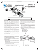
User's Manual

2
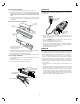
Flow Detector Installation
1. Look for the water fl ow direction arrow on the stick-on sensor strip.
2. Carefully peel off the stick-on sensor strip backing and affi x the sensor strip
long-wise to the cleaned off section of the pipe. Be sure the water fl ow
direction in the pipe matches the fl ow direction arrow on the sensor
strip.
3. Position the red silicone insulator completely over the sensor strip, then
secure the insulator and sensor to the pipe with two evenly spaced wire
ties (included).
Flow detector Module Installation
1. Fit the gray foam pipe insulator over the sensor assembly and onto the pipe
with the sensor cable exiting one end of the pipe insulator.
2. Fit the fl ow detector over the gray foam pipe insulator.
3. Secure the fl ow detector to the pipe using the attached hook and loop strap.
Power Supply Installation
1. Insert the power supply connector into the power input plug on the side of
the fl ow detector.
2. Plug the power supply into a non-switched 120 VAC outlet.
3. The green indicator on the fl ow detector should light.
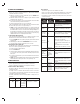
CALIBRATION
Before the fl ow detector can accurately measure the water fl ow in the
monitored pipe, it will need to be calibrated. Perform the following steps to
calibrate the unit.
1. Turn off the water to the home by closing the incoming water line valve at
nearest point to entry of home (typically the valve to turn off water is near
where it enters the home).
2. Press the CALIBRATE button on the fl ow detector. The red and green
indicators will
alternatively blink every second.
3. Wait for the calibration process (about 30 seconds).
4. The system will confi rm that the calibration is completed. by fl ashing the
Green LED three (3) times and then staying on. If the calibration failed, the
Red LED will fl ash three (3) times and stay Red.
5. Turn the water back on to the home.
OPERATION
Once installed and calibrated, the Smart Flow detector will continuously
monitor the water fl owing through the pipe. If water is running continuously at a
rate of approximately ten (10) oz. per minute, an alert will be sent to the Z-Wave
hub. The default Water Flow Time for the Smart Flow detector is 21 minutes.
You can change the Water Flow Time from 14 to 350 minutes (see
Confi guration). The Smart Flow detector will send an alert based on the Water
Flow Time with a variation of up to seven (7) minutes. So out of the box, the
Smart Flow detector will send an alert if water is fl owing for 21 to 28 minutes.
If the Water Flow Time is changed to 14 minutes, an alert will be sent between
14 and 21 minutes.
✓ Note: It may take up to seven (7) minutes for a water fl owing alert to be
cleared.
✓ Note: This product should be tested periodically to make sure it is working
properly. The product, if used properly, may reduce the risk of water
damage. However it may fail to warn for a variety of reasons, including, but
not limited to improper installation or positioning, improper maintenance,
component failures, Z-Wave communication failures, water fl ow may be
outside of the product’s designed range of ten (10) oz. per minute and
certain environmental conditions may impact performance.
FLOW
SENSOR
SILICONE
INSULATOR
COPPER
WATER
PIPE
WATER FLOW
DIRECTIO
N
PEEL OFF
ADHESIVE
BACKING
SECURE SENSOR AND
INSULATOR TO WATER PIPE
WITH TWO ZIP TIES
PLUG POWER
SUPPLY INTO
OUTLET
PLUG POWER
SUPPLY INTO
DETECTOR
HOOK AND LOOP
STRAP
PLUG SENSOR CABLE
INTO DETECTOR
DETECTOR
FLOW DIRECTION
FIT PIPE INSULATOR
OVER SENSOR
STICK TOGETHER
SENSOR