
Installation Instructions

Copyright © 2016 Nortek Security & Control LLC 1
LTE CELL RADIO MODULE
INSTALLATION INSTRUCTIONS
The 2GIG LTE Cell Radio Module is a snap-in, cellular radio module that
provides the 2GIG Control Panel with the ability to send and receive
two (2) -way voice communicaons with the Central Staon
monitoring the security system. It is designed for use with two (2)
External Cellular Antennas which pr
ovides a consistently strong signal
for communicaons.
NOTE: For best performance locate the antenna away from metal.
In addion to providing the Control Panel the ability to transmit
security informaon to online monitoring portals, the cell radio
module allows for delivery of Over-the-Air (OTA) firmware updates to
the Control Panel.
Box Contents
Verify that the package includes the following items:
• 1—LTE Cell Radio Module
• 2—External Cellular Antennas
• 2—#4 Phillips Head Machine Screws and Lock Washers
Requirements
• 2GIG Control Panel with the appropriate firmware version for
your Cell Radio Module
Installing the LTE Cell Radio Module and
Antennas
NOTE: As with all electrical appliances, a shock hazard exists if any
electrical current is connected to the 2GIG Control Panel by AC
power or baery while inserng, removing, or replacing parts.
To ins
tall the Cell Radio Module:
1 Disconnect the AC power supply from its power source.
2 Remove the backplate from the Control Panel.
3 Disconnect the baery from the Control Panel.
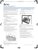
4 Align the Cell Radio Module as shown in the figure below.
5 Use the two (2) screws and lock washers provided to secure the
Cell Radio Module as shown in the figure below.
Figure 1 LTE Cell Radio Module Placement
A = MAIN connector for out-of-panel antenna (in wall or in desk
mount)
B = DIV connector for in-panel antenna
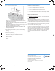
7 Affix both antenna cables to the connectors on top of the Cell
Radio Module as follows:
NOTE: Both antennas must be installed for proper performance.
• Connect one antenna to the MAIN connector and place the
antenna outside the case as shown in Figure 2.
• Connect the other an
tenna to the DIV connector and place it
inside the case.
NOTE: Route the antenna cables so that they do not run across
the top of the module.
8 Pull the loose end of the antenna through the access hole on the
Control Panel’s backplate.
Figure 2 Antenna Placement
9 Replace the Control Panel’s backplate.
Removing an Existing Cell Radio Module and
Antenna
If you are replacing an exisng module with a new LTE Cell Radio
Module, use the steps below.
NOTE: As with all electrical appliances, a shock hazard exists if any
electrical current is connected to the 2GIG Control Panel by AC
power or baery while inserng, removing, or replacing parts.
Removing the Cell Radio Module
To remove the Cell Radio Module:
1 Disconnect the AC power supply from its power source.
2 Remove the backplate from the Control Panel.
3 Disconnect the baery from the Control Panel.
4 Detach the antennas as shown in 1 in the figure below.
For steps, see "Removing an Internal Antenna" on page 2 or
"Removing an External Antenna" on page 2.
5 Remove the screws as shown in 2 in the figure below.
6 Pull the Cell Radio Module out carefully, without bending the pins
as shown in 3 in the figure below.
PRINTER’S INSTRUCTIONS
10013635A LTE-CELL-MODULE-INSTALL-INSTR-en-PRT, 09/16/2016, BLACK, 20LB MEAD BOND, 8.5X11”, TOL. +/- 0.125, SCALE: 1:1, FRONT & BACK, FOLD TO FIT BOX
6 Attach the provided FCC Label to the control panel back cover.