Part No.
Copyright © 2001 Nortel Networks All rights reserved. May 2001. The information in this document is subject to change without notice. The statements, configurations, technical data, and recommendations in this document are believed to be accurate and reliable, but are presented without express or implied warranty. Users must take full responsibility for their applications of any products specified in this document. The information in this document is proprietary to Nortel Networks Inc.
In addition, the program and information contained herein are licensed only pursuant to a license agreement that contains restrictions on use and disclosure (that may incorporate by reference certain limitations and notices imposed by third parties).
Nortel Networks Inc. software license agreement NOTICE: Please carefully read this license agreement before copying or using the accompanying software or installing the hardware unit with pre-enabled software (each of which is referred to as “Software” in this Agreement). BY COPYING OR USING THE SOFTWARE, YOU ACCEPT ALL OF THE TERMS AND CONDITIONS OF THIS LICENSE AGREEMENT. THE TERMS EXPRESSED IN THIS AGREEMENT ARE THE ONLY TERMS UNDER WHICH NORTEL NETWORKS WILL PERMIT YOU TO USE THE SOFTWARE.
own data and information and for maintaining adequate procedures apart from the Software to reconstruct lost or altered files, data, or programs. 4. Limitation of liability.
209418-A
Contents Preface . . . . . . . . . . . . . . . . . . . . . . . . . . . . . . . . . . . . . . . . . . . . . . . . . . . . . . 19 Before you begin . . . . . . . . . . . . . . . . . . . . . . . . . . . . . . . . . . . . . . . . . . . . . . . . . . . . . 19 Text conventions . . . . . . . . . . . . . . . . . . . . . . . . . . . . . . . . . . . . . . . . . . . . . . . . . . . . . 20 How to get help . . . . . . . . . . . . . . . . . . . . . . . . . . . . . . . . . . . . . . . . . . . . . . . . . . . . . .
Contents RFCs . . . . . . . . . . . . . . . . . . . . . . . . . . . . . . . . . . . . . . . . . . . . . . . . . . . . . . . . 40 Standards . . . . . . . . . . . . . . . . . . . . . . . . . . . . . . . . . . . . . . . . . . . . . . . . . . . . 40 SNMP MIB support . . . . . . . . . . . . . . . . . . . . . . . . . . . . . . . . . . . . . . . . . . . . . . . . 41 SNMP trap support . . . . . . . . . . . . . . . . . . . . . . . . . . . . . . . . . . . . . . . . . . . . . . . .
Contents 9 Trunk Configuration screen for Switch S3 . . . . . . . . . . . . . . . . . . . . . . . . . . . . 78 Trunk Configuration screen for Switch S4 . . . . . . . . . . . . . . . . . . . . . . . . . . . . 79 Before you configure trunks . . . . . . . . . . . . . . . . . . . . . . . . . . . . . . . . . . . . . . . . . . 81 Spanning tree considerations for MultiLink Trunks . . . . . . . . . . . . . . . . . . . . . . . . 82 Additional tips about the MultiLink Trunking feature . . . . . . . . . . . . . . .
Contents MultiLink Trunk Configuration Menu screen . . . . . . . . . . . . . . . . . . . . . . . . . . . . 133 MultiLink Trunk Configuration screen . . . . . . . . . . . . . . . . . . . . . . . . . . . . . . 135 MultiLink Trunk Utilization screen . . . . . . . . . . . . . . . . . . . . . . . . . . . . . . . . . 137 Port Mirroring Configuration screen . . . . . . . . . . . . . . . . . . . . . . . . . . . . . . . . . . . 139 Port Statistics screen . . . . . . . . . . . . . . . . . . . . . . . . . . . . .
Contents 11 Electromagnetic emissions . . . . . . . . . . . . . . . . . . . . . . . . . . . . . . . . . . . . . . . . . . . . 181 Electromagnetic immunity . . . . . . . . . . . . . . . . . . . . . . . . . . . . . . . . . . . . . . . . . . . . . 182 Appendix B Installing a Gigabit Interface Converter (GBIC) . . . . . . . . . . . . . . . . . . . . 183 Product description . . . . . . . . . . . . . . . . . . . . . . . . . . . . . . . . . . . . . . . . . . . . . . . . . . 183 GBIC labeling . . . . . . . . . .
Contents 209418-A
Figures Figure 1 BayStack 420 Switch . . . . . . . . . . . . . . . . . . . . . . . . . . . . . . . . . . . . . . . . 25 Figure 2 BayStack 420 Switch front panel . . . . . . . . . . . . . . . . . . . . . . . . . . . . . . . 26 Figure 3 BayStack 420 Switch LED display panel . . . . . . . . . . . . . . . . . . . . . . . . . 28 Figure 4 BayStack 420 Switch back panel . . . . . . . . . . . . . . . . . . . . . . . . . . . . . . . 30 Figure 5 BayStack 420 Switch security feature . . . . . . . . . . .
Figures Figure 30 Choosing the MultiLink Trunk Configuration Menu screen . . . . . . . . . . . . 74 Figure 31 MultiLink Trunk Configuration screen for Switch S1 . . . . . . . . . . . . . . . . . 75 Figure 32 MultiLink Trunk Configuration screen for Switch S2 . . . . . . . . . . . . . . . . . 77 Figure 33 MultiLink Trunk Configuration screen for Switch S3 . . . . . . . . . . . . . . . . . 78 Figure 34 MultiLink Trunk Configuration screen for Switch S4 . . . . . . . . . . . . . . . . .
Figures 15 Figure 65 Port Mirroring Configuration screen . . . . . . . . . . . . . . . . . . . . . . . . . . . . 140 Figure 66 Port Statistics screen . . . . . . . . . . . . . . . . . . . . . . . . . . . . . . . . . . . . . . . 142 Figure 67 System Log screen . . . . . . . . . . . . . . . . . . . . . . . . . . . . . . . . . . . . . . . . . 146 Figure 68 Console/Comm Port Configuration screen . . . . . . . . . . . . . . . . . . . . . . . 148 Figure 69 Renumber Stack Units screen . . . . . . . . .
Figures 209418-A
Tables Table 1 Components on the BayStack 420 Switch front panel . . . . . . . . . . . . . . . 26 Table 2 BayStack 420 Switch LED descriptions . . . . . . . . . . . . . . . . . . . . . . . . . . 29 Table 3 Components on the BayStack 420 Switch back panel . . . . . . . . . . . . . . . 30 Table 4 International power cord specifications . . . . . . . . . . . . . . . . . . . . . . . . . . 31 Table 5 SNMP MIB support . . . . . . . . . . . . . . . . . . . . . . . . . . . . . . . . . . . . . . . . .
Tables Table 30 Monitoring modes . . . . . . . . . . . . . . . . . . . . . . . . . . . . . . . . . . . . . . . . . . 141 Table 31 Port Statistics screen fields . . . . . . . . . . . . . . . . . . . . . . . . . . . . . . . . . . 143 Table 32 System Log screen fields Table 33 Console/Comm Port Configuration screen fields . . . . . . . . . . . . . . . . . . 148 Table 34 Renumber Stack Units screen fields . . . . . . . . . . . . . . . . . . . . . . . . . . . 155 . . . . . . . . . . . . . . . . . .
Preface This guide describes the Nortel Networks* BayStack* 420 10/100/1000 Switch features and uses. The terms “BayStack 420 10/100/1000 Switch” and “BayStack 420 Switch” are used synonymously in this document. You can use the BayStack 420 Switch in: • • A standalone switch configuration. A BayStack 420 Switch-only stack configuration.
Preface Text conventions This guide uses the following text conventions: angle brackets (< >) Indicate that you choose the text to enter based on the description inside the brackets. Do not type the brackets when entering the command. Example: If the command syntax is: ping , you enter: ping 192.32.10.12 bold text Indicates command names and options and text that you need to enter. Example: Enter show ip {alerts | routes}. Example: Use the dinfo command.
Preface 21 italic text Indicates file and directory names, new terms, book titles, and variables in command syntax descriptions. Where a variable is two or more words, the words are connected by an underscore. Example: If the command syntax is: show at valid_route is one variable and you substitute one value for it. screen text Indicates system output, for example, prompts and system messages. Example: Set Trap Monitor Filters separator ( > ) Shows menu paths.
Preface Related publications For more information about using the BayStack 420 Switch, refer to the following publications: • Using the BayStack 420 10/100/1000 Switch (part number 209418-A) Describes how to use the BayStack 420 10/100/1000 Switch for network configuration. • Using Web-Based Management for the BayStack 420 10/100/1000 Switch (part number 211252-A) Describes how to use the Web-based management tool to configure switch features.
Preface 23 You can purchase selected documentation sets, CDs, and technical publications through the Internet at the www1.fatbrain.com/documentation/nortel/ URL. How to get help If you purchased a service contract for your Nortel Networks product from a distributor or authorized reseller, contact the technical support staff for that distributor or reseller for assistance.
Preface 209418-A
Chapter 1 BayStack 420 Switch 25 Chapter 1 BayStack 420 Switch This chapter introduces the BayStack 420 Switch and covers the following topics: • • “Physical description,” next “Features” on page 34 Physical description Figure 1 depicts the front and side views of the BayStack 420 Switch.
Chapter 1 BayStack 420 Switch Front panel Figure 2 shows the configuration of the front panel on the BayStack 420 Switch. Table 1 describes the components on the front panel. For descriptions of the back panel BayStack 420 Switch components, see “Back panel” on page 30.
Chapter 1 BayStack 420 Switch 27 The Console port is a DB-9, RS-232-D male serial port connector. You can use this connector to connect a management station or console/terminal to the BayStack 420 Switch by using a straight-through DB-9 to DB-9 standard serial port cable. You must use a VT100/ANSI-compatible terminal (for cursor control and to enable cursor and functions keys) to use the console port. See Installing the BayStack 420 10/100/1000 Switch for more information.
Chapter 1 BayStack 420 Switch The 10BASE-T/100BASE-TX switch ports also support half- and full-duplex mode operation (refer to Installing the BayStack 420 10/100/1000 Switch). The 10BASE-T/100BASE-TX RJ-45 ports can connect to 10 Mb/s or 100 Mb/s Ethernet segments or nodes. Note: Use only Category 5 copper unshielded twisted pair (UTP) cable connections when connecting 10BASE-T/100BASE-TX ports.
Chapter 1 BayStack 420 Switch 29 Table 2 BayStack 420 Switch LED descriptions Label Type Color State Meaning Power On Power status Green On DC power is available to the switch’s internal circuitry. Off No AC power to switch or power supply failed. Cascade Up Stack mode Off The switch is in standalone mode. On The switch is connected to the upstream unit’. Off The switch is in standalone mode. Green On The switch is connected to the downstream unit.
Chapter 1 BayStack 420 Switch Back panel The switch back panel is shown in Figure 4. Table 3 describes the components on the back panel.
Chapter 1 BayStack 420 Switch 31 AC power receptacle The AC power receptacle accepts the AC power cord (supplied). For installation outside of North America, make sure that you have the proper power cord for your region. Any cord used must have a CEE-22 standard V female connector on one end and must meet the IEC 320-030 specifications. Table 4 lists specifications for international power cords.
Chapter 1 BayStack 420 Switch Caution: Please read immediately. Inspect this power cord and determine if it provides the proper plug and is appropriately certified for use with your electrical system. Immediately discard this cord if it is inappropriate for your country’s electrical system and obtain the proper cord as required by your national electrical codes or ordinances.
Chapter 1 BayStack 420 Switch 33 Advertencia: Sírvase leer inmediatamente. Inspeccione este cable de alimentación eléctrica y determine si viene con el enchufe apropiado y está debidamente certificado para el uso con su sistema eléctrico. Si no cumple con los reglamentos del sistema eléctrico de su país, despójese de este cable de alimentación inmediatamente y obtenga el cable requerido, según las ordenanzas y códigos eléctricos nacionales.
Chapter 1 BayStack 420 Switch Avvertenza: Estrarre il cavo di alimentazione è l'unico sistema per spegnere il dispositivo. Il cavo di alimentazione deve essere sempre collegato in una posizione che permetta l'accesso facile e sicuro in caso di emergenza. Features The BayStack 420 Switch provides wire-speed switching that allows high-performance, low-cost connections to full-duplex and half-duplex 10/100/1000 Mb/s Ethernet local area networks (LANs).
Chapter 1 BayStack 420 Switch 35 Security The BayStack 420 Switch security features provide two levels of security for your local area network (LAN): • • RADIUS-based security—limits administrative access to the switch through user authentication MAC address-based security—limits access to the switch based on allowed source MAC addresses Figure 5 shows a typical campus configuration using the BayStack 420 Switch security features.
Chapter 1 BayStack 420 Switch In this configuration example, the following security measures are implemented: • • The switch — RADIUS-based security is used to limit administrative access to the switch through user authentication (see “RADIUS-based network security” on page 37). — MAC address-based security is used to allow up to 448 authorized stations (MAC addresses) access to one or more switch ports (see “MAC address-based security” on page 37).
Chapter 1 BayStack 420 Switch 37 RADIUS-based network security The RADIUS-based security feature allows you to set up network access control, using the RADIUS (Remote Authentication Dial-In User Services) security protocol. The RADIUS-based security feature uses the RADIUS protocol to authenticate local console and Telnet logins. You will need to set up specific user accounts (user names and passwords, and Service-Type attributes) on your RADIUS server before the authentication process can be initiated.
Chapter 1 BayStack 420 Switch The response can be to send a trap, turn on destination address (DA) filtering, disable the specific port, or any combination of these three options. The MAC address-based security feature is based on Nortel Networks BaySecure LAN Access for Ethernet, a real-time security system that safeguards Ethernet networks from unauthorized surveillance and intrusion.
Chapter 1 BayStack 420 Switch 39 MultiLink Trunking The MultiLink Trunking feature allows you to group multiple ports, two to four together, when forming a link to another switch or server, thus increasing aggregate throughput of the interconnection between two devices, up to 800 Mb/s in full-duplex mode. The BayStack 420 Switch can be configured with up to six MultiLink Trunks in a stack. The trunk members can only be configured within a single unit in the stack.
Chapter 1 BayStack 420 Switch Autosensing is used when the attached device is not capable of autonegotiation or is using a form of autonegotiation that is not compatible with the IEEE 802.3u autonegotiation standard. In this case, because it is not possible to sense the duplex mode of the attached device, the BayStack 420 Switch reverts to half-duplex mode.
Chapter 1 BayStack 420 Switch 41 SNMP MIB support The BayStack 420 Switch supports an SNMP agent with industry standard MIBs, as well as private MIB extensions, which ensures compatibility with existing network management tools. The switch supports the MIB-II (RFC 1213), Bridge MIB (RFC 1493), and the RMON MIB (RFC 1757), which provide access to detailed management statistics.
Chapter 1 BayStack 420 Switch SNMP trap support The BayStack 420 Switch supports an SNMP agent with industry standard SNMPv1 traps, as well as private SNMPv1 trap extensions (Table 6). Table 6 Support SNMP traps Trap name Configurable Sent when linkUp Per port A port’s link state changes to up. linkDown Per port A port’s link state changes to down. authenticationFailure System wide There is an SNMP authentication failure. coldStart Always on The system is powered on.
Chapter 1 BayStack 420 Switch 43 Configuration and switch management The BayStack 420 Switch is shipped directly from the factory ready to operate in any 10BASE-T or 100BASE-TX standard network. You must assign an IP address to the switch or stack, depending on the mode of operation. You can set both addresses by using the console port or BootP, which resides on the switch.
Chapter 1 BayStack 420 Switch Optivity network management software consists of views, most of which are maps that illustrate the interconnections between the segments, rings, and nodes of your network. The views allow you to analyze network performance and fault conditions on the individual segments and specific areas in your network. They can also alert you when a problem has occurred in a specific location. For further information about Optivity, contact your Nortel Networks sales representative.
Chapter 2 Network configuration Use BayStack 420 switches to connect workstations, personal computers (PCs), and servers to each other by connecting these devices directly to the switch, through a shared media hub connected to the switch or by creating a virtual LAN (VLAN) through the switch. This chapter describes the following topics: • • • • • “Network configuration examples,” next “BayStack 420 Switch stack operation” on page 49 “IEEE 802.
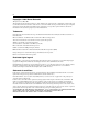
Chapter 2 Network configuration Figure 6 BayStack 420 Switch used as a desktop switch Before After BayStack 420 10BASE-T hub Up to 24 users To Network Center To Network Center Up to 24 users Key 10 Mb/s 100 Mb/s 1000 Mb/s - 23 users share 10 Mb/s (10/24 Mb/s per user) - Network center bottleneck (10 Mb/s bandwidth) - 24 users; each with dedicated 100 Mb/s bandwidth - Network center with dedicated 1 Gb/s full-duplex bandwith 9996EA Segment switch application Figure 7 shows a BayStack 420 Switch
Chapter 2 Network configuration 47 Figure 7 BayStack 420 Switch used as a segment switch After Before 10BASE-T hubs BayStack 420 Server Up to 20 users Server Up to 23 users Up to 23 users Up to 23 users To Network Center Up to 88 users To Network Center Key 10 Mb/s 100 Mb/s 1000 Mb/s - 88 users share 10 Mb/s (10/88 Mb/s per user) - Server bottleneck (10 Mb/s bandwidth) - Network center bottleneck (10 Mb/s bandwidth) -Total of 88 users - Three sets of 23 users; each set shares 10 Mb/s (10/23
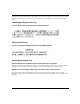
Chapter 2 Network configuration High-density switched workgroup application Figure 8 shows an example of using a BayStack 420 Switch with a high-speed (gigabit) connection to a Nortel Networks Passport* 1100 switch. BayStack 303 and BayStack 304 switches are also shown in this example of a high-density switched workgroup. As shown in Figure 8, the Passport 1100 switch is used as a backbone switch, connecting to the BayStack 420 Switch with an optional (1000BASE-SX) GBIC for maximum bandwidth.
Chapter 2 Network configuration 49 Figure 8 Configuring power workgroups and a shared media hub BayStack 420 F BayStack 303 switch Passport 1100 switch Server BayStack 304 switch Key 10 Mb/s 100 Mb/s 1000 Mb/s (Gigabit) 9998EB BayStack 420 Switch stack operation You can connect up to eight BayStack 420 switches to provide uninterrupted connectivity for up to 192 ports. The entire stack is manageable as a single unit.
Chapter 2 Network configuration Base unit The base unit is the unique stack unit that you configure with the Unit Select switch on the front panel. One BayStack 420 Switch in the stack must be configured as the base unit; all other units in the stack must have their Unit Select switch set to Off (see “Unit select switch” on page 49). You can assign any single BayStack 420 Switch as the base unit.
Chapter 2 Network configuration 51 If another unit in the stack is assigned as the base unit, the MAC address of the new base unit (with offset) now applies to the stack configuration. The original stack IP address still applies to the new base unit.
Chapter 2 Network configuration Figure 9 Stack up configuration example Out 1 100-240 V50-60Hz 2A 100-240 V50-60Hz 2A In Unit 7 Cascade Out 100-240 V50-60Hz 2A In Unit 6 Cascade Out 100-240 V50-60Hz 2A In Unit 5 Cascade Out 100-240 V50-60Hz 2A In Unit 4 Cascade Out 100-240 V50-60Hz 2A In Unit 3 Cascade Out 100-240 V50-60Hz 2A In Unit 2 Cascade Out 2 Unit 8 Cascade Out 100-240 V50-60Hz 2A In Unit 1 Cascade Out 3 In In 4 10001EA Table 7 describes the stack up configurat
Chapter 2 Network configuration 53 Figure 10 Stack down configuration example In 1 100-240 V50-60Hz 2A 100-240 V50-60Hz 2A In Unit 2 Cascade Out 100-240 V50-60Hz 2A In Unit 3 Cascade Out 100-240 V50-60Hz 2A In Unit 4 Cascade Out 100-240 V50-60Hz 2A In Unit 5 Cascade Out 100-240 V50-60Hz 2A In Unit 6 Cascade Out 100-240 V50-60Hz 2A In Unit 7 Cascade Out 2 Unit 1 Cascade Out 100-240 V50-60Hz 2A In Unit 8 Cascade Out In 3 Out 4 10002EA Table 8 describes the stack down conf
Chapter 2 Network configuration In any stack configuration, the following applies: • • • • • When you apply power to the stack, the base unit initializes and the entire stack powers up as a single logical unit. You can attach an RS-232 communications cable to the console port of any switch in the stack.
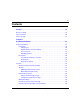
Chapter 2 Network configuration 55 Figure 11 Port-based VLAN example VLAN 1 VLAN 2 BayStack 420 10004EA IEEE 802.1Q tagging BayStack 420 switches operate in accordance with the IEEE 802.1Q tagging rules. Important terms used with the 802.1Q tagging feature are: • • • • • VLAN identifier (VID)—the 12-bit portion of the VLAN tag in the frame header that identifies an explicit VLAN.
Chapter 2 Network configuration • • • • • Untagged member—a port that has been configured as an untagged member of a specific VLAN. When an untagged frame exits the switch through an untagged member port, the frame header remains unchanged. When a tagged frame exits the switch through an untagged member port, the tag is stripped and the tagged frame is changed to an untagged frame. Tagged member—a port that has been configured as a member of a specific VLAN.
Chapter 2 Network configuration 57 Figure 12 Default VLAN settings 802.1Q Switch VLAN 1 Port 1 Port 2 Port 3 Port 4 Port 5 Port 6 Port 7 Port 8 PVID = 1 DA CRC SA Incoming untagged packet Data Outgoing untagged packet (unchanged) CRC Data SA DA Key By default: All ports are assigned PVID = 1 All ports are untagged members of VLAN 1 BS45010A When you configure VLANs, you configure the switch ports as tagged or untagged members of specific VLANs (see Figure 13 through Figure 21).
Chapter 2 Network configuration Figure 13 Port-based VLAN assignment Data SA Port 4 CRC DA Port 2 Port 3 Tagged member of VLAN 2 Port 5 Port 1 PVID = 2 Untagged packet 802.1Q Switch Before Port 6 Port 7 Port 8 Untagged member of VLAN 2 BS45011A As shown in Figure 14, the untagged packet is marked (tagged) as it leaves the switch through port 5, which is configured as a tagged member of VLAN 2.
Chapter 2 Network configuration 59 In Figure 15, tagged incoming packets are assigned directly to VLAN 2 because of the tag assignment in the packet. Port 5 is configured as a tagged member of VLAN 2, and port 7 is configured as an untagged member of VLAN 2. Figure 15 802.1Q tag assignment Data Tag SA Port 4 CRC DA Before Port 2 Port 3 Tagged member of VLAN 2 Port 5 Port 1 PVID = 2 Tagged packet 802.
Chapter 2 Network configuration VLANs spanning multiple switches You can use VLANs to segment a network within a switch. When you connect multiple switches, it is possible to connect users of one VLAN with users of that same VLAN in another switch. However, the configuration guidelines depend on whether both switches support 802.1Q tagging. With 802.1Q tagging enabled on a port for a VLAN, all frames leaving the port for that VLAN are marked as belonging to that specific VLAN.
Chapter 2 Network configuration 61 Because there is only one link between the two switches, the Spanning Tree Protocol (STP) treats this configuration as any other switch-to-switch connection. For this configuration to work properly, both switches must support the 802.1Q tagging protocol. VLANS spanning multiple untagged switches Figure 18 shows VLANs spanning multiple untagged switches. In this configuration, Switch S2 does not support 802.
Chapter 2 Network configuration To connect multiple VLANs across switches with redundant links, you must disable the STP on all participating switch ports. Figure 19 shows possible consequences of enabling the STP when using VLANs between untagged (non-802.1Q tagged) switches.
Chapter 2 Network configuration 63 Shared servers BayStack 420 switches allow ports to exist in multiple VLANs for shared resources, such as servers, printers, and switch-to-switch connections. It is also possible to have resources exist in multiple VLANs on one switch as shown in Figure 20. In this example, clients on different broadcast domains share resources. The broadcasts from ports configured in VLAN 3 can be seen by all VLAN port members of VLAN 3.
Chapter 2 Network configuration Figure 21 VLAN broadcast domains within the switch S1 VLAN 3 VLAN 2 Port 2 Port 4 Port 10 PVID = 2 VLAN 1 Port 8 PVID = 3 V2 V2 V2 V3 Port 6 Port 11 PVID = 1 V1 V2 Key VLAN 1 (PVID = 1) VLAN 2 (PVID = 2) VLAN 3 (PVID = 3) BS45019A For example, to create a broadcast domain for each VLAN shown in Figure 21, configure each VLAN with a port membership, and each port with the appropriate PVID/VLAN association: • • • • • • Ports 8, 6, and 11 are untagged membe
Chapter 2 Network configuration 65 To configure the VLAN port membership for VLAN 1: 1 Select Switch Configuration from the BayStack 420 Switch Main Menu (or press w). 2 From the Switch Configuration Menu, select VLAN Configuration (or press v). 3 From the VLAN Configuration Menu select VLAN Configuration (or press v). The default VLAN Configuration screen opens (Figure 22).
Chapter 2 Network configuration Ports 2, 4, 6, 8, 10, and 11 are now untagged members of VLAN 3 as shown in Figure 21 on page 64. Figure 23 VLAN Configuration screen example To configure the PVID (port VLAN identifier) for port 8: 1 From the VLAN Configuration screen, press [Ctrl]-R to return to the VLAN Configuration Menu. 2 From the VLAN Configuration Menu, select VLAN Port Configuration (or press c). The default VLAN Port Configuration screen opens (Figure 24).
Chapter 2 Network configuration 67 Figure 24 Default VLAN Port Configuration screen example Figure 25 shows the VLAN Port Configuration screen after it is configured to support the PVID assignment for port 8, as shown in Figure 21 on page 64 (Port Name is optional). The PVID/VLAN association for VLAN 3 is now PVID = 3.
Chapter 2 Network configuration Figure 25 VLAN Port Configuration screen example VLAN workgroup summary This section summarizes the VLAN workgroup examples discussed in the previous sections of this chapter. As shown in Figure 26, Switch S1 (BayStack 420 Switch) is configured with multiple VLANs: • • • Ports 1, 6, 11, and 12 are in VLAN 1. Ports 2, 3, 4, 7, and 10 are in VLAN 2. Port 8 is in VLAN 3. Because S4 does not support 802.
Chapter 2 Network configuration 69 Figure 26 VLAN configuration spanning multiple switches BayStack 420 Non-802.1Q tagging switch S4 S2 Both ports are tagged members of VLAN 1 and VLAN 2 Untagged ports (STP disabled) BayStack 420 S1 V1 Non-802.
Chapter 2 Network configuration VLAN configuration rules VLANs operate according to specific configuration rules. When creating VLANs, consider the following rules that determine how the configured VLAN reacts in any network topology: • • • • All ports that are involved in port mirroring must have memberships in the same VLANs. If a port is configured for port mirroring, the port’s VLAN membership cannot be changed.
Chapter 2 Network configuration 71 Figure 27 Switch-to-switch trunk configuration example BayStack 420 S1 T1 F BayStack 420 S2 T2 BayStack 420 S3 10009EA You can configure each of the trunks shown in Figure 27 with up to four switch ports to provide up to 800 Mb/s aggregate bandwidth through each trunk, in full-duplex mode.
Chapter 2 Network configuration Figure 28 Switch-to-server trunk configuration example FS1 FS2 T1 S1 BayStack 420 10010EA Client/server configuration using MultiLink Trunks Figure 29 shows an example of how MultiLink Trunking can be used in a client/server configuration. In this example, both servers connect directly to Switch S1. FS2 is connected through a trunk configuration (T1). The switch-to-switch connections are through trunks (T2, T3, T4, and T5).
Chapter 2 Network configuration 73 Figure 29 Client/server configuration example FS2 FS1 T1 BayStack 420 S1 F T2 T3 S2 BayStack 420 T4 S3 T5 BayStack 420 S4 BayStack 420 10011EA The trunk configuration screens for switches S1 to S4 are shown in “Trunk configuration screen examples” following this section. For detailed information about configuring trunks, see “MultiLink Trunk Configuration screen” on page 135.
Chapter 2 Network configuration Trunk configuration screen for Switch S1 Switch S1 is set up with five trunk configurations: T1, T2, T3, T4, and T5. To set up the S1 trunk configuration: Choose MultiLink Trunk Configuration (or press t) from the MultiLink Trunk Configuration Menu screen (Figure 30). Figure 30 Choosing the MultiLink Trunk Configuration Menu screen The MultiLink Trunk Configuration Menu screen opens (Figure 31).
Chapter 2 Network configuration 75 Figure 31 MultiLink Trunk Configuration screen for Switch S1 Switch S1 is configured as follows: • • Trunk (read only) indicates the trunks (1 to 6) that correspond to the switch ports specified in the Trunk Members fields. Trunk Members (Unit/Port) indicates the ports that can be configured, in each row, to create the corresponding trunk: Note: The Unit value (in the Unit/Port field) is not configurable when the switch is operating standalone.
Chapter 2 Network configuration • • — Ports 15, 17, 19, and 21 are assigned as trunk members of trunk 1. — Ports 25 and 26 are assigned as trunk members of trunk 2. — Ports 2 and 4 are assigned as trunk members of trunk 3. — Ports 14 and 16 are assigned as trunk members of trunk 4. — Ports 22 and 24 are assigned as trunk members of trunk 5. STP Learning indicates the spanning tree participation setting for each of the trunks: — Trunks 1 through 4 are enabled for Normal STP Learning.
Chapter 2 Network configuration 77 Figure 32 shows the MultiLink Trunk Configuration screen for Switch S2. Figure 32 MultiLink Trunk Configuration screen for Switch S2 Switch S2 is configured as follows: • • • • • Trunk (read only) indicates the trunks (1 to 6) that correspond to the switch ports specified in the Trunk Members fields.
Chapter 2 Network configuration • Trunk Name indicates optional fields for assigning names to the corresponding configured trunks. The names chosen for this example provide meaningful information to the user of this switch (for example, S2:T2 to S1 indicates that Trunk 1, in Switch S2, connects to Switch 1). Trunk Configuration screen for Switch S3 As shown in Figure 29 on page 73, Switch S3 is set up with one trunk configuration (T4). This trunk connects directly to Switch S1.
Chapter 2 Network configuration 79 Switch S3 is configured as follows: • • • • • • Trunk (read only) indicates the trunk (1 to 6) that corresponds to the switch ports specified in the Trunk Members fields. Trunk Members (Unit/Port) indicates the ports that can be configured, in each row, to create the corresponding trunk. Ports 1 and 3 are assigned as trunk members of trunk 1. STP Learning indicates the spanning tree participation setting for each of the trunks.
Chapter 2 Network configuration Figure 34 shows the MultiLink Trunk Configuration screen for Switch S4. Figure 34 MultiLink Trunk Configuration screen for Switch S4 Switch S4 is configured as follows: • • • • • • 209418-A Trunk (read only) indicates the trunk (1 to 6) that corresponds to the switch ports specified in the Trunk Members fields. Trunk Members (Unit/Port) indicates the ports that can be configured, in each row, to create the corresponding trunk.
Chapter 2 Network configuration 81 The names chosen for this example provide meaningful information to the user (for example, S4:T5 to S1 indicates that Trunk 1, in Switch S4, connects to Switch 1). Before you configure trunks When you create and enable a trunk, the trunk members (switch ports) take on certain settings necessary for correct operation of the MultiLink Trunking feature.
Chapter 2 Network configuration Spanning tree considerations for MultiLink Trunks The spanning tree Path Cost parameter is recalculated based on the aggregate bandwidth of the trunk. For example, Figure 35 shows a four-port trunk (T1) with two port members operating at 100 Mb/s and two at 10 Mb/s. Trunk T1 provides an aggregate bandwidth of 220 Mb/s. The Path Cost for T1 is 4 (Path Cost = 1000/ LAN speed, in Mb/s).
Chapter 2 Network configuration 83 The switch can also detect trunk member ports that are physically misconfigured. For example, in Figure 36, trunk member ports 2, 4, and 6 of Switch S1 are configured correctly to trunk member ports 7, 9, and 11 of Switch S2. The Spanning Tree Port Configuration screen for each switch shows the port state field for each port in the Forwarding state.
Chapter 2 Network configuration If Switch S2’s trunk member port 11 is physically disconnected and then reconnected to port 13, the Spanning Tree Port Configuration screen for Switch S1 changes to show port 6 in the Blocking state (Figure 37).
Chapter 2 Network configuration 85 Additional tips about the MultiLink Trunking feature When you create a MultiLink Trunk, the individual trunk members (the specific ports that make up the trunk) logically connect and react as a single entity. For example, if you change spanning tree parameters for any trunk member, the spanning tree parameters for all trunk members change. All configured trunks are indicated in the Spanning Tree Configuration screen.
Chapter 2 Network configuration Figure 38 provides a sample Port Mirroring Configuration screen. Note that the displayed screens do not show all of the screen prompts that precede some actions.
Chapter 3 Using the console interface This chapter describes how to configure and manage the BayStack 420 Switch using the menu-driven console interface (CI).
Chapter 3 Using the console interface Using the CI menus and screens The CI menus and screens provide options that allow you to configure and manage BayStack 420 switches. Help prompts at the bottom of each menu and screen explain how to enter data in the highlighted field and how to navigate the menus and screens. The Console port default settings are: 9600 baud with eight data bits, one stop bit, and no parity as the communications format, with flow control set to disabled.
Chapter 3 Using the console interface 89 To return to the previous menu, press [Ctrl]-R. To go to the next screen in a series, press [Ctrl]-N. To return to the main menu at any time, press [Ctrl]-C. Press [Backspace] to delete entered text. Options that appear in brackets (for example, [Enabled]) are user-settable options. Screen fields and descriptions Figure 39 shows a map of the CI screens. The remainder of this chapter describes the CI screens and their fields, beginning with the main menu.
Chapter 3 Using the console interface The CI screens for your specific switch model will show the correct model name in the main menu screen title and the correct number of ports and port types in the Port Configuration screen. Note: The field values shown in the CI screens in this section are provided as examples only. Main menu This section describes the options available from the CI main menu (Figure 40). The CI screens and submenus for these options are described in the following sections.
Chapter 3 Using the console interface 91 Figure 40 Console interface main menu Table 9 describes the CI main menu options. Table 9 Console interface main menu options Option Description IP Configuration/ Setup... Displays the IP Configuration/Setup screen (see “IP Configuration/Setup screen” on page 94). This screen allows you to set or modify IP configuration parameters. SNMP Configuration... Displays the SNMP Configuration screen (see “SNMP Configuration screen” on page 99).
Chapter 3 Using the console interface Table 9 Console interface main menu options (continued) Option Description Switch Configuration... Displays the Switch Configuration Menu screen (see “Switch Configuration Menu screen” on page 103).
Chapter 3 Using the console interface 93 Table 9 Console interface main menu options (continued) Option Description Reset to Default Settings Resets the switch to the factory default configuration settings. This option is followed by a screen prompt that precedes the action. Enter Yes to reset the switch to the factory default configuration settings; enter No to abort the option: • If the switch is participating in a stack configuration, you can reset the entire stack.
Chapter 3 Using the console interface IP Configuration/Setup screen The IP Configuration/Setup screen (Figure 41) allows you to set or modify the BayStack 420 Switch IP configuration parameters. Data that you enter in the user-configurable fields takes effect as soon as you press [Enter]. To open the IP Configuration/Setup screen: Choose IP Configuration/Setup (or press i) from the main menu. Figure 41 IP Configuration/Setup screen Table 10 describes the IP Configuration/Setup screen fields.
Chapter 3 Using the console interface 95 Table 10 IP Configuration/Setup screen fields Field Description BootP Request Mode One of four modes of operation for BootP. (See “Choosing a BootP request mode” on page 96 for details about the four modes.) Default Value BootP Disabled Range BootP Disabled, BootP When Needed, BootP Always, BootP or Last Address Configurable Column header for the user-configurable IP configuration fields in this screen.
Chapter 3 Using the console interface Table 10 IP Configuration/Setup screen fields (continued) Field Description In-Band Subnet Mask The subnet address mask associated with the in-band IP address shown on the screen (see In-Band Switch IP address field). Network routers use the subnet mask to determine the network or subnet address portion of a host’s IP address.
Chapter 3 Using the console interface 97 BootP When Needed Allows the switch to request an IP address if one has not already been set from the console terminal. When selected, this mode operates as follows: • • When the IP data is entered from the console terminal, the data becomes the in-use address of the switch and BootP requests are not broadcast. The switch can be managed using this in-band IP address.
Chapter 3 Using the console interface BootP Disabled Allows the switch to be managed only by using the IP address set from the console terminal. When selected, this mode operates as follows: • • The switch does not broadcast BootP requests, regardless of whether an IP address is set from the console terminal. The switch can be managed only by using the in-band switch IP address set from the console terminal.
Chapter 3 Using the console interface 99 SNMP Configuration screen The SNMP Configuration screen (Figure 42) allows you to set or modify the SNMP configuration parameters. To open the SNMP Configuration screen: Choose SNMP Configuration (or press m) from the main menu. Figure 42 SNMP Configuration screen Table 11 describes the SNMP Configuration screen fields.
Chapter 3 Using the console interface Table 11 SNMP Configuration screen fields (continued) Field Description Read-Write Community String The community string used for in-band read-write SNMP operations. Trap #1 IP Address 1 Community String Authentication Trap Autotopology Default Value private Range Any ASCII string of up to 32 printable characters Number one of four trap IP addresses. Successive trap IP address fields are numbered 2, 3, and 4.
Chapter 3 Using the console interface 101 Figure 43 System Characteristics screen Table 12 describes the System Characteristics screen fields. Table 12 System Characteristics screen fields Field Description Operation Mode Read-only field that indicates the operation mode of the unit, for example: • When the unit is part of a stack configuration, the (read-only) field indicates the unit is operational in a stack, and lists the current unit number of this switch.
Chapter 3 Using the console interface Table 12 System Characteristics screen fields (continued) Field Description Reset Count A read-only field that indicates the number of resets since the operational firmware was first loaded on the switch. Last Reset Type Power Status Default Value 1 Range 0 to 232 -1 (4,294,967,295) A read-only field that indicates the last type of reset.
Chapter 3 Using the console interface 103 Switch Configuration Menu screen The Switch Configuration Menu screen (Figure 44) allows you to set or modify your switch configuration. Choose Switch Configuration (or press w) from the main menu to open the Switch Configuration Menu screen (Table 13).
Chapter 3 Using the console interface Table 13 describes the Switch Configuration Menu options. Table 13 Switch Configuration Menu options Option Description MAC Address Table Displays the MAC Address Table screen (see “MAC Address Table screen” on page 105). This screen allows you to view all MAC addresses and their associated port or trunk that the switch has learned, or to search for a particular MAC address (to see if the switch has learned the address). MAC Address Security Configuration...
Chapter 3 Using the console interface 105 Table 13 Switch Configuration Menu options (continued) Option Description Clear All Port Statistics Allows you to clear all port statistics.
Chapter 3 Using the console interface Figure 45 MAC Address Table screen Table 14 describes the MAC Address Table screen fields. Table 14 MAC Address Table screen fields Field Description Aging Time Specifies how long a learned MAC address remains in the switch’s forwarding database. If an entry is inactive for a period of time that exceeds the specified aging time, the address is removed.
Chapter 3 Using the console interface 107 MAC Address Security Configuration Menu screen The MAC Address Security Configuration Menu screen (Figure 46) allows you to specify a range of system responses to unauthorized network access to your switch. The system response can range from sending a trap to disabling the port. The network access control is based on the MAC addresses of the authorized stations. You can specify a list of up to 448 MAC addresses that are authorized to access the switch.
Chapter 3 Using the console interface Table 15 describes the MAC Address Security Configuration Menu options. Table 15 MAC Address Security Configuration Menu options Option Description MAC Address Security Configuration... Displays the MAC Address Security Configuration screen (see “Table 15 describes the MAC Address Security Configuration Menu options.” on page 108). This screen allows you to Enable or Disable the MAC Address Security feature. MAC Address Security Port Configuration...
Chapter 3 Using the console interface 109 Figure 47 MAC Address Security Configuration screen Table 16 describes the MAC Address Security Configuration screen fields. Table 16 MAC Address Security Configuration screen fields Field Description MAC Address Security When this field is set to enabled, the software checks source MAC addresses of packets that arrive on secure ports against MAC addresses listed in the MAC Address Security Table for allowed membership.
Chapter 3 Using the console interface Table 16 MAC Address Security Configuration screen fields (continued) Field Description Partition Port on Intrusion This field value determines how the switch reacts to an intrusion event. When Detected: an intrusion even is detected (see MAC Address Security field description) the specified switch port is set to Disabled (partitioned from other switch ports).
Chapter 3 Using the console interface 111 Table 16 MAC Address Security Configuration screen fields (continued) Field Description Clear by Ports This field clears the specified port (or ports) that are listed in the Allowed Source Port(s) field of the MAC Address Security Table screen (see “MAC Address Security Table screens” on page 118).
Chapter 3 Using the console interface Figure 48 MAC Security Port Configuration screen (1 of 2) Figure 49 MAC Security Port Configuration screen (2 of 2) 209418-A
Chapter 3 Using the console interface 113 Table 17 describes the MAC Security Port Configuration screen fields. Table 17 MAC Security Port Configuration screen fields Field Description Port Displays a numbered port list. Trunk Displays the trunk number if the port is a member of that trunk. Default Security blank field This field value determines whether or not security is enabled or disabled on the port level or switch level.
Chapter 3 Using the console interface Figure 50 MAC Address Security Port Lists screens MAC Address Security Port Lists Entry ----S1 Screen 1 Port List --------[ ] S2 [ ] S3 ] S4 [ Entry ----S8 [ S5 S9 [ ] [ ] S6 S10 [ ] ] S7 S11 [ ] Entry[ ----S15 [ ] MAC Address Security Port Lists Screen 2 Port List --------[ ] ] MAC Address Security Port Lists Screen 3 Port List --------[ ] More...
Chapter 3 Using the console interface 115 Figure 51 MAC Address Security Port Lists screen Table 18 describes the MAC Address Security Port Lists screen fields. Table 18 MAC Address Security Port Lists screen fields Field Description Entry This field indicates the port list number (S1 to S32) that corresponds to the values you set in the Port List field. Port List This field allows you to create a port list that you can use as an “Allowed Source” in the MAC Address Security Table screen.
Chapter 3 Using the console interface A unit/port number list is composed of one or more list items, each of which can be a single number or a range of numbers (where the numbers represents one or more ports). If a list item is preceded by a number and then a slash (/), the number represents a stack unit. For example, 1/1-7,2/1-7,2/9,3/1-4,4/12 is a valid unit/port number list (see entry S1 in Figure 51 on page 115).
Chapter 3 Using the console interface 117 As an alternative method instead, you can highlight the field and then enter +2/9 [Return]. The existing field keeps the previous list and adds the new port number (2/9) between ports 2/7 and 3/14. (If you choose to add port 2/8 to the existing port number list, the field accepts the new port 2/8 but shows the new port number list field as: 1/3,2/7-8,3/1-4.
Chapter 3 Using the console interface MAC Address Security Table screens The MAC Address Security Table screens allow you specify the ports that each MAC address is allowed to access. You must also include the MAC addresses of any routers that are connected to any secure ports. There are 16 available MAC Address Security Table screens (Figure 52) that you can use to create up to 448 MAC address entries (28 per screen).
Chapter 3 Using the console interface 119 Figure 53 MAC Address Security Table screen Table 19 describes the MAC Address Security Table screen fields. Table 19 MAC Address Security Table screen fields Field Description Find an Address Allows you to search for a specific MAC address that is used in any of the MAC Address Security Table screens. MAC Address Allows you to specify up to 448 MAC addresses that are authorized to access the switch.
Chapter 3 Using the console interface Table 19 MAC Address Security Table screen fields (continued) Field Description Default Range - (Blank field) A single unit/port or a port list value (for example, 1/3, 1/6, 3/4, S1, S5, etc.). 1 Multicast address -- Note that the first octet of any Multicast address will always be an odd number. VLAN Configuration Menu screen The VLAN Configuration Menu screen (Figure 54) allows you to select the appropriate screen to configure up to 32 VLANs.
Chapter 3 Using the console interface 121 To open the VLAN Configuration Menu: Choose VLAN Configuration (or press v) from the Switch Configuration Menu screen. Figure 54 VLAN Configuration Menu screen Table 20 describes the VLAN Configuration Menu options. Table 20 VLAN Configuration Menu options Option Description VLAN Configuration... Displays the VLAN Configuration screen (see “VLAN Configuration screen” on page 122). This screen allows you to set up VLAN workgroups. VLAN Port Configuration...
Chapter 3 Using the console interface VLAN Configuration screen The VLAN Configuration screen (Figure 55) allows you to create and assign VLAN port memberships to standalone or stacked unit ports. You can create port-based and policy-based VLANs for the following purposes: • IEEE 802.1Q port-based VLANs allow you to explicitly configure switch ports as VLAN port members. When you create a port-based VLAN, you assign a Port VLAN Identifier (PVID) manually, or use Auto PVID to assign it automatically.
Chapter 3 Using the console interface 123 Figure 55 VLAN Configuration screen Table 21 describes the VLAN Configuration screen fields. Table 21 VLAN Configuration screen fields Field Description Create VLAN Allows you to set up or view configured VLAN workgroups. Enter the number of the new VLAN you want to create or view, then press [Return]. The Port Membership fields indicate the corresponding VLAN workgroup configuration, if configured. Dashes (-) indicate no VLAN Members are configured.
Chapter 3 Using the console interface Table 21 VLAN Configuration screen fields (continued) Field VLAN Name Description Default blank field Range 2 to 4094 Allows you to assign a name field to configured VLANs. Default VLAN # (VLAN number) Range Any ASCII string of up to 16 printable characters Management VLAN Allows you to assign any VLAN as the management VLAN. VLAN 1 is the default management VLAN for the switch. To set this field, the VLAN State field value must be Active.
Chapter 3 Using the console interface 125 Table 21 VLAN Configuration screen fields (continued) Field Description • When the Tagging field is set to Tagged Trunk, you can set the Port Membership field as a tagged port member (T) or as a non-VLAN port member (-). The Port Membership fields are displayed in six-port groups (for example, 1-6, 7-12, 13-18). The number of ports displayed depends on the switch model or type of optional GBIC installed in the Uplink Module slot.
Chapter 3 Using the console interface Figure 56 VLAN Port Configuration screen Table 22 describes the VLAN Port Configuration screen fields. Table 22 VLAN Port Configuration screen fields Field Description Unit Allows you to select a switch in your stack. To view another switch, type its switch number and press [Enter], or press the spacebar to toggle the switch numbers. Port Allows you to select the number of the port you want to view or configure.
Chapter 3 Using the console interface 127 Table 22 VLAN Port Configuration screen fields (continued) Field Description PVID Associates this port with a specific VLAN. For example, a port with a PVID of 3 assigns all untagged frames received on this port to VLAN 3. Tagging Default 1 Range 1 to 4094 Allows you to assign VLAN Port Membership tagging options to this port, as follows: • Auto PVID Untagged Access: Any VLAN that this port is a member of will not be 802.1Q tagged.
Chapter 3 Using the console interface Figure 57 VLAN Display by Port screen Table 23 describes the VLAN Display by Port screen fields. Table 23 VLAN Display by Port screen fields Field Description Unit Allows you to select a switch in your stack. To view another switch, type its switch number and press [Enter], or press the spacebar to toggle the switch numbers. Port Allows you to select the number of the port you want to view.
Chapter 3 Using the console interface 129 Port Configuration screen The Port Configuration screen (Figures 58 and 59) allows you to configure specific switch ports or all switch ports. You can enable or disable the port status of specified switch ports, set the switch ports to autonegotiate for the highest available speed of the connected station, or set the speed for selected switch ports (autonegotiation is not supported on fiber optic ports).
Chapter 3 Using the console interface Figure 59 Port Configuration screen (2 of 2) Table 24 describes the Port Configuration screen fields. Table 24 Port Configuration screen fields Field Description Port Indicates the switch port numbers that correspond to the field values in that row of the screen (for example, the field values in row 2 apply to switch port 2).
Chapter 3 Using the console interface 131 Table 24 Port Configuration screen fields (continued) Field Description LnkTrap Allows you to control whether link up/link down traps are sent to the configured trap sink from the switch. Autonegotiation Speed/Duplex1 Default Value On Range On, Off When enabled, sets the corresponding port speed to match the best service provided by the connected station, up to 100 Mb/s in full-duplex mode. This field is disabled for all fiber optic ports.
Chapter 3 Using the console interface Figure 60 High Speed Flow Control Configuration Table 25 describes the High Speed Flow Control Configuration screen fields. Table 25 High Speed Flow Control Configuration screen fields Field Description Unit Allows you to select the unit number (when stacking is configured) to view or configure.
Chapter 3 Using the console interface 133 Choosing a high speed flow control mode The high speed flow control feature allows you to control traffic and avoid congestion on the Gigabit full-duplex link. If the receive port buffer becomes full, the BayStack 420 Switch issues a flow-control signal to the device at the other end of the link to suspend transmission. When the receive buffer is no longer full, the switch issues a signal to resume the transmission.
Chapter 3 Using the console interface You can monitor the bandwidth usage for the trunk member ports within each trunk. For more information about configuring MultiLink Trunks, see “MultiLink Trunks” on page 70. Note: When a trunk is not active (Trunk Status field set to Disabled), configuration changes do not take effect until you set the Trunk Status field to Enabled.
Chapter 3 Using the console interface 135 Table 26 describes the MultiLink Trunk Configuration Menu options. Table 26 MultiLink Trunk Configuration Menu options Option Description MultiLink Trunk Configuration... Displays the MultiLink Trunk Configuration screen (Figure 62). This screen allows you to configure up to six MultiLink Trunks within a standalone switch or within a stack configuration. You can group up to four switch ports together to form each trunk. MultiLink Trunk Utilization...
Chapter 3 Using the console interface Figure 62 MultiLink Trunk Configuration screen Table 27 describes the MultiLink Trunk Configuration screen fields. Table 27 MultiLink Trunk Configuration screen fields Field Description Trunk Column header for the read-only fields in this screen. The read-only data displayed in the Trunk column indicates the trunk (1 to 6) that corresponds to the switch ports specified in the user-configurable Trunk Members fields.
Chapter 3 Using the console interface 137 Table 27 MultiLink Trunk Configuration screen fields (continued) Field Description STP Learning The STP Learning column contains a single field for each row that, when enabled, allows the specified trunk to participate in the spanning tree. This setting overrides those of the individual trunk members. Fast is the same as Normal, except that the state transition timer is shortened to two seconds.
Chapter 3 Using the console interface Figure 63 MultiLink Trunk Utilization screen (1 of 2) Figure 64 MultiLink Trunk Utilization screen (2 of 2) 209418-A
Chapter 3 Using the console interface 139 Table 28 describes the MultiLink Trunk Utilization screen fields. Table 28 MultiLink Trunk Utilization screen fields Field Description Trunk Column header for the read-only fields in this screen. The read-only data displayed in this column indicates the trunk (1 to 6) that corresponds to the switch ports specified in the Port field. Traffic Type Allows you to choose the traffic type to be monitored for percent of bandwidth utilization (see Range).
Chapter 3 Using the console interface To open the Port Mirroring Configuration screen: Choose Port Mirroring Configuration (or press i) from the Switch Configuration Menu screen. Figure 65 Port Mirroring Configuration screen Table 29 describes the Port Mirroring Configuration screen fields.
Chapter 3 Using the console interface 141 Table 29 Port Mirroring Configuration screen fields (continued) Field Description Monitor Unit/Port Indicates the port number (of the specified unit) that is designated as the monitor port. Unit/Port X Default Value Zero-length string Range 1 to 8/ 1 to 28 (depending on model type) Indicates one of the ports (of the specified unit) that will be monitored by the designated port monitor when one of the port-based monitoring modes is selected.
Chapter 3 Using the console interface To open the Port Statistics screen: Choose Display Port Statistics (or press d) from the Switch Configuration Menu screen. Figure 66 Port Statistics screen Table 31 describes the Port Statistics screen fields. Note: In a stacked configuration, the Port Statistics screen appears in a slightly different format when the port selected in the Unit/Port field is configured with a GBIC.
Chapter 3 Using the console interface 143 Table 31 Port Statistics screen fields Field Description Unit Only appears if the switch is participating in a stack configuration. The field allows you to select the number of the unit you want to view or configure. To view or configure another unit, type its unit number and press [Enter], or press the spacebar on your keyboard to toggle the unit numbers. Port Allows you to select the number of the port you want to view or reset to zero.
Chapter 3 Using the console interface Table 31 Port Statistics screen fields (continued) Field Description 128-255 bytes Received column: Indicates the total number of 128-byte to 255-byte packets received on this port. Transmitted column: Indicates the total number of 128-byte to 255-byte packets transmitted successfully on this port. 256-511 bytes Received column: Indicates the total number of 256-byte to 511-byte packets received on this port.
Chapter 3 Using the console interface 145 Table 31 Port Statistics screen fields (continued) Field Description The following field values appear only when the port selected in the Unit/Port field is configured with a GBIC. Pause Frames (Port 25 only) Transmitted column: Indicates the total number of pause frames transmitted on this port. Pause frames cause the transmitting port to temporarily suspend the transmission of packets when the receiving port’s frame buffer is full (Gigabit ports only).
Chapter 3 Using the console interface Figure 67 System Log screen Table 32 describes the System Log screen fields. Table 32 System Log screen fields Field Description Unit This field only appears if the switch is participating in a stack configuration. The field allows you to select the unit number of the BayStack 420 Switch you want to view.
Chapter 3 Using the console interface 147 Table 32 System Log screen fields (continued) Field Description Display configuration complete? This field allows you to determine whether the configuration information received from NVRAM/DRAM (depending on what is selected in the Display Messages From field) is complete. Use the spacebar to toggle between the options. Default No Range No, Yes Clear Messages From This field allows you to clear the information messages from DRAM, NVRAM or both.
Chapter 3 Using the console interface Figure 68 Console/Comm Port Configuration screen Table 33 describes the Console/Comm Port Configuration screen fields. Table 33 Console/Comm Port Configuration screen fields Field Description Comm Port Data Bits A read-only field that indicates the current console/comm port data bit setting. Comm Port Parity A read-only field that indicates the current console/comm port parity setting.
Chapter 3 Using the console interface 149 Table 33 Console/Comm Port Configuration screen fields (continued) Field Description Achtung: Bei Auswahl einer Baud rate, die nicht mit der Baudrate des Konsolenterminals übereinstimmt, geht die Kommunikation mit der Konsolenschnittstelle verloren, wenn Sie die Eingabetaste drücken. Stellen Sie in diesem Fall das Konsolenterminal so ein, daß es mit der neuen Einstellung der Service-Schnittstelle übereinstimmt.
Chapter 3 Using the console interface Table 33 Console/Comm Port Configuration screen fields (continued) Field Description Console Stack Password Type Enables password protection for accessing the console interface (CI) of any participating switch in a stack configuration through a console terminal. If you set this field to Required, you can use the Logout option to restrict access to the CI of any stack unit.
Chapter 3 Using the console interface 151 Table 33 Console/Comm Port Configuration screen fields (continued) Field Description Default Value: secure Range: Any ASCII string of up to 15 printable characters Caution: If you change the system-supplied default passwords, be sure to write the new passwords down and keep them in a safe place. If you forget the new passwords, you cannot access the console interface. In that case, contact Nortel Networks for help.
Chapter 3 Using the console interface Table 33 Console/Comm Port Configuration screen fields (continued) Field Description Console Read-Only Stack Password When the Console Switch Password field is set to Required (for Telnet, for Console, or for Both), this field allows read-only password access to the CI of any participating switch in a stack configuration.
Chapter 3 Using the console interface 153 Table 33 Console/Comm Port Configuration screen fields (continued) Field Description Attenzione: In caso di modifica delle password predefinite nel sistema, assicurarsi di annotare le nuove password e di conservarle in un luogo sicuro. Nel caso in cui le nuove password vengano dimenticate, non sarà possibile accedere all'interfaccia della console. In tal caso, contattare la Nortel Networks per avere assistenza.
Chapter 3 Using the console interface Renumber Stack Units screen The Renumber Stack Units screen (Figure 69) allows you to renumber the units configured in the stack. When selected, this option identifies the unit number of each unit in the stack configuration by lighting the corresponding number of (100 Mb/s port) LEDs on each unit for approximately 10 seconds. For example, unit 3 will display three LEDs.
Chapter 3 Using the console interface 155 Table 34 describes the Renumber Stack Units screen fields. Table 34 Renumber Stack Units screen fields Field Description Current Unit Number Read-only fields listing the current unit number of each of the configured stack units. The entries in this column are displayed in order of their current physical cabling with respect to the base unit, and can show nonconsecutive unit numbering if one or more units were previously moved or modified.
Chapter 3 Using the console interface Figure 70 Hardware Unit Information screen Spanning Tree Configuration Menu screen The Spanning Tree Configuration Menu screen (Figure 71) allows you to view spanning tree parameters and configure individual switch ports to participate in the spanning tree algorithm (STA). To modify any of the spanning tree parameters, see your SNMP documentation.
Chapter 3 Using the console interface 157 Figure 71 Spanning Tree Configuration Menu screen Table 35 describes the Spanning Tree Configuration Menu options. Table 35 Spanning Tree Configuration Menu options Option Description Spanning Tree Port Configuration... Displays the Spanning Tree Port Configuration screen (see “Spanning Tree Port Configuration screen” on page 158).
Chapter 3 Using the console interface Spanning Tree Port Configuration screen The Spanning Tree Port Configuration screen allows you to configure individual switch ports or all switch ports for participation in the spanning tree. Note: If spanning tree participation of any trunk member is changed (enabled or disabled), the spanning tree participation of all members of that trunk is changed similarly.
Chapter 3 Using the console interface 159 Figure 73 Spanning Tree Port Configuration screen (2 of 2) Table 36 describes the Spanning Tree Port Configuration screen fields. Table 36 Spanning Tree Port Configuration screen fields Field Description Unit This field only appears if the switch is participating in a stack configuration. The field allows you to select the number of the unit you want to view.
Chapter 3 Using the console interface Table 36 Spanning Tree Port Configuration screen fields (continued) Field Description Participation Allows you to configure any (or all) of the switch ports for Spanning tree participation. When an individual port is a trunk member (see Trunk field), changing this setting for one of the trunk members changes the setting for all members of that trunk. You should consider how this can change your network topology before you change this setting.
Chapter 3 Using the console interface 161 Spanning Tree Switch Settings screen The Spanning Tree Switch Settings screen (Figure 74) allows you to view spanning tree parameter values for the BayStack 420 Switch. To open the Spanning Tree Switch Settings screen: Choose Display Spanning Tree Switch Settings (or press d) from the Spanning Tree Configuration Menu screen.
Chapter 3 Using the console interface Table 37 describes the Spanning Tree Switch Settings parameters. Table 37 Spanning Tree Switch Settings parameters Parameter Description Bridge Priority Indicates the management-assigned priority value of the bridge ID in hexadecimal notation, which is the most significant byte of the bridge ID. The STA uses this parameter to determine the root bridge (or designated bridge).
Chapter 3 Using the console interface 163 Table 37 Spanning Tree Switch Settings parameters (continued) Parameter Description Forward Delay Indicates the Forward Delay parameter value that the root bridge is currently using. This value specifies the amount of time that the bridge ports remain in the Listening and Learning states before entering the Forwarding state.
Chapter 3 Using the console interface TELNET Configuration screen The TELNET Configuration screen (Figure 75) allows a user at a remote console terminal to communicate with the BayStack 420 Switch as if the console terminal were directly connected to it. You can have up to four active Telnet sessions at one time. To open the TELNET Configuration screen: Choose TELNET Configuration (or press t) from the main menu.
Chapter 3 Using the console interface 165 Table 38 describes the TELNET Configuration screen fields. Table 38 TELNET Configuration screen fields Field Description TELNET Access Allows a user remote access to the CI through a Telnet session. Login Timeout Login Retries Inactivity Timeout Event Logging Default Value: Enabled Range: Enabled, Disabled Specifies the amount of time a user has to enter the correct password at the console-terminal prompt.
Chapter 3 Using the console interface Table 38 TELNET Configuration screen fields (continued) Field Description Allowed Source Specifies up to 10 user-assigned host IP addresses that are allowed Telnet access to the IP Address CI. Default Value: 0.0.0.0 (no IP address assigned) Range: Four-octet dotted-decimal notation, where each octet is represented as a decimal value, separated by a decimal point Allowed Source Specifies up to 10 user-assigned allowed source address masks.
Chapter 3 Using the console interface 167 Precaución: No interrumpa la alimentación del dispositivo durante el proceso de descarga del software. Si lo hace, puede alterar la imagen de la programación (firmware). Attenzione: Non interrompere l'alimentazione elettrica al dispositivo durante il processo di scaricamento del software. In caso di interruzione, l'immagine firmware potrebbe danneggiarsi.
Chapter 3 Using the console interface Figure 76 Software Download screen for a BayStack 420 Switch stack Table 39 describes the Software Download screen fields. Table 39 Software Download screen fields Field Description BayStack 420 The BayStack 420 Switch software image load file name. Image Filename NOTE: Certain software releases may require you to download two images: the boot code image and the agent image.
Chapter 3 Using the console interface 169 Table 39 Software Download screen fields (continued) Field Description TFTP Server IP Address The IP address of your TFTP load host. Default Value 0.0.0.0 (no IP address assigned) Range Four-octet dotted-decimal notation, where each octet is represented as a decimal value, separated by a decimal point Start TFTP Load Specifies whether to start the download of the switch software image (default is No).
Chapter 3 Using the console interface You can retrieve the configuration parameters of a standalone switch or an entire stack and use the retrieved parameters to automatically configure a replacement switch or stack. Certain requirements apply when automatically configuring a switch or stack using this feature (see “Requirements” on page 172). You must set up the file on your TFTP server and set the filename read/write permission to enabled before you can save the configuration parameters.
Chapter 3 Using the console interface 171 Table 40 describes the Configuration File Download/Upload screen fields. Table 40 Configuration File Download/Upload screen fields Field Description Configuration Image Filename The file name you have chosen for the configuration file. Choose a meaningful file name that will allow you to identify the file for retrieval when required. The file must already exist on your TFTP server and must be read/ write enabled.
Chapter 3 Using the console interface Requirements The following requirements apply to the Configuration File feature: • The Configuration File feature can only be used to copy standalone switch configuration parameters to other standalone switches or to copy stack configuration parameters to other stack configurations. For example, you cannot duplicate the configuration parameters of a unit in a stack configuration and use it to configure a standalone switch.
Chapter 4 Troubleshooting This chapter describes how to isolate and diagnose problems with your BayStack 420 Switch and covers the following topics: • “Interpreting the LEDs,” next • “Diagnosing and correcting problems” on page 175 — Normal power-up sequence — Port connection problems The chapter topics lead you through a logical process for troubleshooting the BayStack 420 Switch.
Chapter 4 Troubleshooting Figure 78 LED display panel BayStack 420-24T Switch 1 3 5 7 9 11 13 15 17 19 21 23 10/100 Link Activity HDX/FDX 12/100 Link Activity Base HDX/FDX 2 4 6 8 10 12 14 16 18 20 22 24 Unit Set 9991EA Table 42 BayStack 420 Switch LED descriptions Label Type Color State Meaning Power On Power status Green On DC power is available to the switch’s internal circuitry. Off No AC power to switch or power supply failed.
Chapter 4 Troubleshooting 175 Table 42 BayStack 420 Switch LED descriptions (continued) Label Type Color Activity Port activity HD/FD Duplex Mode State Meaning Green Blinking Indicates network activity for the corresponding port. A high level of network activity can cause the LEDs to appear to be on continuously. Green On/ Off The port is configured to full duplex. The port is configured to half duplex.
Chapter 4 Troubleshooting Avvertenza: Per evitare lesioni fisiche dovute a scariche pericolose di corrente, non rimuovere mai il coperchio superiore del dispositivo. I componenti interni non possono essere manipolati dall’utente. Normal power-up sequence In a normal power-up sequence, the LEDs appear as follows: 1 After power is applied to the switch, the Pwr (Power) LED turns on within 5 seconds.
Chapter 4 Troubleshooting 177 Table 43 Corrective actions (continued) Symptom Probable cause Corrective action The Activity LED for a connected port is off or does not blink (and you have reason to believe that traffic is present). The switch is experiencing a port connection problem. See “Port connection problems” next. The switch’s link partner is not autonegotiating properly.
Chapter 4 Troubleshooting In both situations, the BayStack 420 Switch “autosenses” the speed of the connected station and, by default, reverts to half-duplex mode. If the connected station is operating in full-duplex mode, it cannot communicate with the switch. To correct this mode mismatch problem: 1 Use the Port Configuration screen to disable autonegotiation for the suspect port (see “Port Configuration screen” on page 129).
Appendix A Technical specifications This appendix provides technical specifications for the BayStack 420 10/100/ 1000 Switch. Environmental Table 44 lists environmental specifications for the BayStack 420 Switch.
Appendix A Technical specifications Table 45 Electrical parameters (continued) Parameter Electrical specification Input current 1 A @ 100 VAC 0.5 A @ 240 VAC Maximum thermal output 250 BTU/hr Physical dimensions Table 46 lists physical dimensions for the BayStack 420 Switch. Table 46 Physical dimensions Parameter Specifications Height 1.75 in (4.5 cm) Width 17.125 in (43.5 cm) Depth 8.0 in (20.32 cm) Weight 6.2 lb (2.
Appendix A Technical specifications 181 Network protocol and standards compatibility The following are protocols and standards used by the BayStack 420 Switch: • • • • • IEEE 802.3 10BASE-T (ISO/IEC 8802-3, Clause 14) IEEE 802.3u 100BASE-TX (ISO/IEC 8802-3, Clause 25) IEEE 802.1Q (VLAN Tagging) IEEE 802.1z (Gigabit) IEEE 802.
Appendix A Technical specifications Electromagnetic immunity The BayStack 420 Switch meets the EN50082-1:1997 standard.
Appendix B Installing a Gigabit Interface Converter (GBIC) This appendix describes how to install and remove a Gigabit Interface Converter (GBIC). It also provides a description of the GBIC, the GBIC label, and GBIC specifications. Product description GBICs are hot-swappable input/output enhancement components designed for use with Nortel Networks products to allow Gigabit Ethernet ports to link with fiber optic networks.
Appendix B Installing a Gigabit Interface Converter (GBIC) Figure 79 Types of GBICs GBIC model with extractor tabs GBIC model with extractor handle 9702FA GBICs are shipped with a protective rubber plug in the connectors. Leave the plug in place when no cables are connected to the GBIC. GBIC labeling The Nortel Networks label on a typical GBIC (Figure 80) contains a Nortel Networks serial number, a bar code, a manufacturer’s code, an interface type, and a part number.
Appendix B Installing a Gigabit Interface Converter (GBIC) 185 GBIC Models Table 48 lists the available Nortel Networks GBIC models. Table 48 Nortel Networks GBIC models Model number Product number Description 1000BASE-SX AA1419001 Short wavelength 550 m 1000BASE-LX AA1419002 Long wavelength 5 km 1000BASE-XD AA1419003 Extended distance 50 km 1000BASE-ZX AA1419004 Extended distance 70 km GBIC specifications GBIC specifications are listed in Table 49.
Appendix B Installing a Gigabit Interface Converter (GBIC) Table 50 describes standards, connectors, cabling, and distance for the Model 1000BASE-SX GBIC. Table 50 Model 1000BASE-SX GBIC specifications Type Standards Specifications Conformity to the following standards: 802.3z, 1000BASE-SX Connectors Duplex SC fiber optic connector Cabling 62.5 µm MMF optic cable 50 µm MMF optic cable Distance 902 ft. (275 m) using 62.5 µm MMF optic cable 1804 ft.
Appendix B Installing a Gigabit Interface Converter (GBIC) 187 Table 51 describes standards, connectors, cabling, and distance for the Model 1000BASE-LX GBIC. Table 51 Model 1000BASE-LX GBIC specifications Type Specifications Standards Conformity to the following standards: 802.3z, 1000BASE-LX Connectors Duplex SC fiber optic connector Cabling 62.5 µm MMF optic cable 50 µm MMF optic cable 10 µm SMF optic cable Distance 1804 ft. (550 m) using 62.5 µm MMF optic cable 1804 ft.
Appendix B Installing a Gigabit Interface Converter (GBIC) 1000BASE-XD The Model 1000BASE-XD GBIC provides Gigabit Ethernet connectivity using SC duplex single-mode fiber connectors. High-performance optical transceivers enable Gigabit Ethernet link distances up to 50 kilometers (km) over single-mode fiber. The ports operate in full-duplex mode only. Table 52 describes standards, connectors, cabling, and distance for the Model 1000BASE-XD GBIC.
Appendix B Installing a Gigabit Interface Converter (GBIC) 189 1000BASE-ZX The Model 1000BASE-ZX GBIC provides Gigabit Ethernet connectivity using SC duplex single-mode fiber connectors. High-performance optical transceivers enable Gigabit Ethernet link distances up to 70 km over single-mode fiber cable. The ports operate in full-duplex mode only. Table 53 describes standards, connectors, cabling, and distance for the Model 1000BASE-ZX GBIC.
Appendix B Installing a Gigabit Interface Converter (GBIC) Note: When shorter lengths of single-mode fiber cable are used, there is a risk of overloading the receiver. It may be necessary to insert an in-line optical attenuator in the link to prevent overloading, as follows: • Insert a 10dB in-line optical attenuator between the fiber optic cable plant and the receiving port on the 1000BASE-ZX GBIC, at each end of the link, if the fiber optic cable span is less than 25 km.
Appendix B Installing a Gigabit Interface Converter (GBIC) 191 Installing a GBIC GBIC bays are covered by spring-loaded filler panels that rotate out of the way as you push the GBIC into place. You can install or replace a GBIC in a BayStack 420 Switch without turning off power to the switch. Warning: Fiber optic equipment can emit laser or infrared light that can injure your eyes. Never look into an optical fiber or connector port. Always assume that fiber optic cables are connected to a light source.
Appendix B Installing a Gigabit Interface Converter (GBIC) To install a GBIC: 1 Remove the GBIC from its protective packaging. 2 Insert the GBIC into the slot on the BayStack switch (Figure 81). GBICs are keyed to prevent improper insertion. If the GBIC resists pressure, do not force it. Remove it, turn it over, and reinsert it. Figure 81 Installing a GBIC 9703FA 3 Press on the front of the GBIC until it snaps into place. 4 Remove the rubber plug to connect cables.
Appendix C Quick configuration for MultiLink Trunking If you are a system administrator with experience configuring BayStack 420 Switch MultiLink Trunking, use the flowchart in Figure 83 on page 194 as a quick configuration guide. The flowchart refers you to the “configuration rules” appropriate for this feature. To open the MultiLink Trunk Configuration screen: Choose MultiLink Trunk Configuration (or press t) from the MultiLink Trunk Configuration Menu screen.
Appendix C Quick configuration for MultiLink Trunking Figure 83 Configuring MultiLink Trunks MultiLink Trunk Configuration screen Are all trunk members configured? No Configure trunk members (see "MultiLink Trunking Configuration Rules"). Yes Is trunk STP Enabled? No Configure STP field. Yes Is trunk Enabled? No Enable Trunk Status field (see "MultiLink Trunking Configuration Rules").
Appendix D Connectors and pin assignments This appendix describes the BayStack 420 Switch port connectors and pin assignments. RJ-45 (10BASE-T/100BASE-TX) port connectors The RJ-45 port connectors (Figure 84) are wired as MDI-X ports to connect end stations without using crossover cables. (See “MDI and MDI-X devices” on page 196 for information about MDI-X ports.) For 10BASE-T connections, use Category 3 (or higher) UTP cable. For 100BASE-TX connections, use only Category 5 UTP cable.
Appendix D Connectors and pin assignments Table 54 lists the RJ-45 (8-pin modular) port connector pin assignments.
Appendix D Connectors and pin assignments 197 MDI-X to MDI cable connections BayStack 420 Switch switches use MDI-X ports that allow you to connect directly to end stations without using crossover cables (Figure 85).
Appendix D Connectors and pin assignments Figure 86 MDI-X to MDI-X cable connections BayStack 420 Switch 1 8 T R 8 1 8 Switch or hub 8 1 1 1 RX+ 1 1 RX+ 1 2 RX- 2 2 RX- 2 3 TX+ 3 3 TX+ 3 4 4 4 4 5 5 5 5 6 TX- 6 6 7 7 7 7 8 8 8 8 MDI-X port Crossover cable TX- T R 6 MDI-X port BS45057B DB-9 (RS-232-D) Console/Comm Port connector The DB-9 Console/Comm Port connector (Figure 87) is configured as a data communications equipment (DCE) connector.
Appendix D Connectors and pin assignments 199 Table 55 lists the DB-9 Console port connector pin assignments.
Appendix D Connectors and pin assignments 209418-A
Appendix E Default settings Table 56 lists the factory default settings for the BayStack 420 Switch according to the console interface (CI) screens and fields for the settings. Table 56 Factory default settings Field Default setting Appears in this CI screen BootP Request Mode BootP Disabled “IP Configuration/Setup screen” on page 94 In-Band Stack IP Address 0.0.0.0 (no IP address assigned) In-Band Switch IP Address 0.0.0.0 (no IP address assigned) In-Band Subnet Mask 0.0.0.
Appendix E Default settings Table 56 Factory default settings (continued) Field Default setting Appears in this CI screen Aging Time 300 seconds “MAC Address Table screen” on page 105 Find an Address 00-00-00-00-00-00 (no MAC address assigned) MAC Address Security Disabled MAC Address Security SNMP-Locked Disabled Partition Port on Intrusion Detected: Disabled Partition Time 0 seconds (the value 0 indicates forever) “MAC Address Security Configuration Menu screen” on page 107 DA Filte
Appendix E Default settings 203 Table 56 Factory default settings (continued) Field Default setting Appears in this CI screen Subnet Addr 0.0.0.0. Subnet Mask 0.0.0.0.
Appendix E Default settings Table 56 Factory default settings (continued) Field Default setting Appears in this CI screen Monitoring Mode Disabled “Port Mirroring Configuration screen” on page 139 Monitor/Unit Port Zero-length string Unit/Port X Zero-length string Unit 1 Port 1 Console Port Speed 9600 Baud Console Switch Password Not Required Console Stack Password Not Required Console Read-Only Switch Password user Console Read-Write Switch Password secure Console Read-Only St
Appendix E Default settings 205 Table 56 Factory default settings (continued) Field Default setting Appears in this CI screen Forward Delay 15 seconds (read only) Bridge Hello Time 2 seconds (read only) Bridge Maximum Age Time 20 seconds (read only) Bridge Forward Delay 15 seconds (read only) TELNET Access Enabled Login Timeout 1 minute Login Retries 3 Inactivity Timeout 15 minutes Event Logging All Allowed Source IP Address (10 user-configurable fields) First field: 0.0.0.
Appendix E Default settings 209418-A
Appendix F Sample BootP configuration file This appendix provides a sample BootP configuration file. The BootP server searches for this file, called bootptab (or BOOTPTAB.TXT, depending on your operating system), which contains the site-specific information (including IP addresses) needed to perform the software download and configuration. You can modify this sample BootP configuration file or create one of your own.
Appendix F Sample BootP configuration file # Caution # # Omitting a Forward slash (/) when the entry is continued to the next # line, can cause the interruption of the booting process or the # incorrect image file to download. Always include forward slashes # where needed. # # Important Note: # # If a leading zero (0) is used in the IP address it is calculated as an # octal number. If the leading character is "x" (upper or lower case), # it is calculated as a hexadecimal number.
Index A Bridge Priority field 162 Actual Hello Interval 162 Broadcasts field 143 Aging Time field 106 Business Policy Switch front panel 26 Allowed Source IP Address field 166 Allowed Source Mask field 166 Authentication Trap field 100 autonegotiation description 39 modes 177 troubleshooting 177 C Clear All Port Statistics option 105 Collisions field 144 Comm Port Data Bits field 148 Comm Port Parity field 148 Autonegotiation field 131 Comm Port Stop Bits field 148 autosense description 39 C
Index conversation steering 39 dimensions 185 disposal 190 handling 190 labels 184 Model 1000BASE-LX 185, 186 1000BASE-SX 185, 186 1000BASE-XD 185, 188 1000BASE-ZX 185, 189 specifications 185 storing 190 crossover cable 197 customer support 23 D DB-9 console/comm port connector 198 Default Gateway field 96 default settings 201 Deferred Packets field 144 Designated Root field 162 Display Event Log option 92 Display Port Statistics option 104 Display Spanning Tree Switch Settings option 157 Gigabit
Index O Link field 130 Login Retries field 165 Login Timeout field 165 Logout option 93 optical attenuators, when to use 190 mulitmode fiber, in long distance applications 187 options Clear All Port Statistics 105 Console/Comm Port Configuration 92 Display Event Log 92 Display Port Statistics 104 Display Spanning Tree Switch Settings 157 IP Configuration 91 Logout 93 MAC Address Table 104 MultiLink Trunk Configuration 104 Port Configuration 104 Port Mirroring Configuration 104 Reset 91, 92 Reset to Def
Index Nortel Networks StackProbe 39 image upgrades 38 Port Mirroring Configuration option 104 Software Download option 92 Port Mirroring Configuration screen 139 Spanning Tree Configuration Menu 156 Port Statistics screen 141 Spanning Tree Configuration option 92 power cord warnings (multilingual) 32 Spanning Tree Port Configuration option 157 power cords 31 Spanning Tree Port Configuration screen 158 power-up sequence 176 Spanning Tree Switch Settings screen 161 Priority field 160 spec
Index Local MDA Type 102 MAC Address 101 Operational Mode 101 Power Status 102 Reset Count 102 Size of Stack 101 sysContact 102 sysDescr 102 sysLocation 102 sysName 102 sysObjectID 102 sysServices 102 sysUpTime 102 T technical specifications 179 technical support 23 213 tutorial IEEE 802.1Q tagging 55 IEEE 802.