
Communication Server Large System Installation and Commissioning


Installing DC power Page 113 of 456
Communication Server 1000M and Meridian 1 Large System Installation and Commissioning
Procedure 7
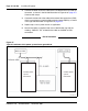
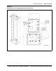
Installing and connecting the power plant frame ground leads
1 Use the appropriate two-hole lug to connect one end of a cable to the
frame ground plate at the top of the frame for a top-fed system or at the
bottom for a bottom-fed system, as shown in Figure 38 on page 115.
Apply the appropriate torque (refer to Table 4 for torque values).
Note: Refer to Note 2 and Table 3 on page 112 for the recommended
cable size.
11 mm
(7/16 in.)
14
20
400
425
5110
5120
13 mm (1/2 in.) 13
20
550
575
6110
6140
16 mm (5/8 in.)
(see note)
11 920 7350
19 mm (3/4 in.)
(see note)
10 1400 9300
22 mm (7/8 in.)
(see note)
9 1950 11100
25 mm (1 in.)
(see note)
8 2580 12900
Note: Bolt sizes 6 mm to 25 mm (5/8 in. to 1 in.) apply to Large Candeo
only.
If Then
The power system shares a frame ground (FG)
collector cable with other equipment
go to step 2.
The power system does not share an FG
collector cable with other equipment
go to step 3.
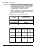
Table 4
Torque values for bolted connections (Part 2 of 2)
Bolt size Threads/inch Torque (in.-lb) Tension (lb)