
Communication Server Large System Installation and Commissioning


Page 126 of 456 Installing DC power
NN43021-310 Standard 02.01 December 2007
c. Connect the wires to the matching connections on the terminal block
on the junction box.
i. Connect the red wires to – BAT 0, – BAT 1, – BAT 2, and
– BAT 3.
ii. Connect the black wires to + BATRTN 0, + BATRTN 1,
+ BATRTN 2, and + BATRTN 3.
iii. Connect the orange or white wire to LRTN.
7 For installations that do not use a junction box:
a. Route two red wires between the power plant and the pedestal of the
column being wired.
b. Route two black wires between the power plant and the pedestal of
the column being wired.
c. Route one (orange or white) wire for the logic return ground (LRTN)
between the power plant and the pedestal of the column being wired.
d. Route the wires within the cable-tie saddles and under the cable
restraint bar at the base of the pedestal.
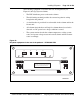
8 Connect wires to the PDU.
a. Connect a red wire for each module to – BAT 0, – BAT 1, – BAT 2,
and – BAT 3 on the connection block.
b. Connect a black wire for each module to + BATRTN 0, + BATRTN 1,
+ BATRTN 2, and + BATRTN 3 on the connection block.
c. Connect the (orange or white) wire to the LRTN terminal on the
connection block.
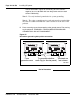
9 Connect wires to the power plant.
a. Connect the red wires to the first two circuit breakers in the main
control/distribution panel. See Figure 46 for PDU to Large Candeo
DC Power Plant connections. Each new column connects the next
two available circuit breakers.
Note: If only two modules are used in the column, make sure the CB2
and CB3 circuit breakers are set to OFF.
b. Connect the black wires to the ground bus/LRE.
c. Connect the orange or white wire to the ground bus/LRE.