
Communication Server Large System Installation and Commissioning


Installing DC power Page 131 of 456
Communication Server 1000M and Meridian 1 Large System Installation and Commissioning
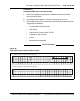
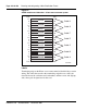
Figure 47
UEM to 8B/2R or 8B/4R master power cabinet connections
TB1 in Power distribution unit
-VE Distribution Rail
Positive Bus
Logic Return Equalizer,
LRE (functional earth)
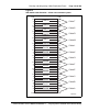
12345678
Red wires
Black wires
To Test Jack Frame (TJF)
16 sq mm green/yellow
Master Power Cabinet(s)
Each output is rated at 30 A
maximum. Maximum total
output is 150 A.
Power alarm cable
(NT8D46AV)
Factory installed
(16 sq mm
green/yellow)
Alarm terminal
(3 off)
J4 in
system
monitor
(XSM)
553-AAA1513
Orange wire
(10 sq mm)
To CB4 (blower)
CB0 (module 0),
& CB1 (module 1)
To CB2 (module 2)
& CB3 (module 3)
To connections
in pedestal
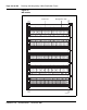
- BAT - BAT - BAT - BAT + RTN + RTN + RTN + RTN LRTN
0
12
30
12
3
Note: Optional four-feed wiring shown