
Communication Server Large System Installation and Commissioning


Page 138 of 456 Planning and designating a Main Distribution Frame
NN43021-310 Standard 02.01 December 2007
Installing the Krone cross-connect system (UK)
In the Krone cross-connect system, one terminating strip holds ten pairs of
cable. When cross-connecting a 25-pair cable on this system, eight of the
ten terminating points are used on each strip. One 25-pair cable, therefore,
occupies three terminating strips:
8 pairs per strip by 3 strips = 24 pairs
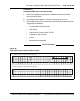
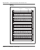
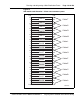
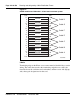
Card allocations
Figures 51 and 52 provide module card allocations for the Krone
cross-connect system.
Procedure 12 describes how to install the Krone Test Jack Frame for the UK.
Procedure 12
Installing the Krone Test Jack Frame (UK)
1 Refer to the equipment layout plan to determine where to place the
cross-connect terminal.
2 Lay out the terminal blocks.
3 Attach labels on the cross-connect terminal to indicate the terminal blocks
assigned to the following:
• Analog line cards
• DC15/AC15/RAN/PAG cards
• Data Access cards
•AUX wiring
• Power Failure Transfer Units
• Digital line cards
• Telephones
• Exchange line trunk cards
• Direct Dialing Inward trunk cards
• Miscellaneous equipment
End of Procedure