
Communication Server Large System Installation and Commissioning


Page 152 of 456 Configuring the system monitor
NN43021-310 Standard 02.01 December 2007
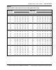
Figure 62
System monitor to system monitor serial link cabling
Power failure transfer control
The system monitor can be cabled to the MDF to provide power failure
transfer control or additional alarms. The cable used is the NT8D46BH, EH,
or DH and it is plugged into J3 on the system monitor. With the same J3
connector, the system monitor can be used with a variety of cables.
AC power control
The system monitor can also monitor and control an AC-powered UPS.
Connector J4 is used for this interface. Three cables are available for
connecting to a UPS: NT8D46AQ, NT8D46AJ, and NT8D46AU.
DC power observation
The system monitor can also work with DC power supplies. A J4 connector
monitors the rectifiers. Cable requirements depend on the battery distribution
box in use. With the Candeo power system, a NT8D46xx cable interfaces
from the connector J4 of the Large System's system monitor to the Candeo's
System Manager alarm output ports. Refer to “Alarm interfacing to Candeo”
on page 165 for additional information.
Pedestal
J5 J6
Master XSM
Column 0
NT8D46AL NT8D46AP
n=63 maximum
Column 1
Pedestal
J5 J6
Slave XSM
Column n
J5 J6
Slave XSM
Pedestal
553-7551