
Communication Server Large System Installation and Commissioning


Configuring the system monitor Page 169 of 456
Communication Server 1000M and Meridian 1 Large System Installation and Commissioning
Procedure 17
Configuring the alarm ports
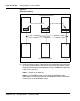
1 Select “Alarm Severity and Output” from the System Manager display
screen.
2 Under “Alarm Name”, select the line with “AC Fail”, and change “Output
Port” to 1.
3 Under “Alarm Name”, select the line with “Major”, and change “Output
Port” to 2 (by default it should already be 2).
4 Under “Alarm Name”, select the line with “Low Float”, and change “Output
Port” to Port 3.
5 All other “Output Ports” should be set to “None”.
Note: For more detailed information refer to the Alarms section in the
Candeo Power System User Guide (P0914425).
End of Procedure
Customizing alarms
Under “Alarm Severity and Outputs”, the ports and severity can be
configured per customers requirements. If the customer wishes they can
utilize signals DCON1, DCON2 and DCON3 by connecting them to other
available “No Connect” ports (connect commons on J8 to the battery return
bus) and customize as desired.
Under the alarm output screen the relay state is defaulted to “not energized”
when alarm is on. To change the relay state an engineering password is
required. Contact Astec support for a temporary password to change this
field. After the setting has been changed use the normally open contacts when
wiring J8.
Note: For further information on all alarms that can be configured for
the Candeo, see the Alarms section in the Candeo Power Systems User
Guide (P0914425) and Candeo SP 48300 Power System AP6C55AA
User Manual (P7000154).