
Communication Server Large System Installation and Commissioning


Cabling Common Equipment in a Single Group system Page 195 of 456
Communication Server 1000M and Meridian 1 Large System Installation and Commissioning
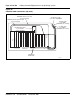
Figure 79
CP PIV Core and Network backplanes
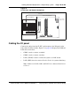
Cabling the I/O panel
Connect the cables from the CP PIV card faceplate to the I/O panel on the
back of the Core/Net modules. Figure 78 on page 194 displays the COM and
LAN cable connections.
• COM1 is used to connect a terminal.
• COM2 is used to connect a modem.
• LAN 1 (ELAN) is used to connect the system to a LAN switch.
• LAN 2 (HSP) is used to connect Core 0 to Core 1 for system redundancy.
Note: If there is no LAN, LAN 1 and LAN 2 are connected from Core 0
to Core 1.
553-9473
Network backplane
Core backplane
ED
System Monitor
(XSM) connections
J1J2
J3
AB
j3 slot 9 port 0 j4 slot 9 port 0
Group 0
Group 1Group 2
Group 3Group 4Group 5
Group 6
Group 7
j3
slot 9
port 1
j4
slot 9
port 1
j3
slot 10
port 0
j4
slot 10
port 0
j3
slot 10
port 1
j4
slot 10
port 1
j3
slot 11
port 0
j4
slot 11
port 0
j3
slot 11
port 1
j4
slot 11
port 1
j3
slot 12
port 0
j4
slot 12
port 0
j3
slot 12
port 1
j4
slot 12
port 1
NT4N89 cable
NT4N29 cable
NT4N29 cable