
Communication Server Large System Installation and Commissioning


Page 196 of 456 Cabling Common Equipment in a Single Group system
NN43021-310 Standard 02.01 December 2007
Procedure 24
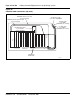
Installing the CP PIV to I/O panel cables
1 Connect COM1 on the CP PIV faceplate to J25 on the I/O panel with cable
NT4N88AA.
2 Connect COM2 on the CP PIV faceplate to J21 on the back of the I/O
panel with cable NT4N88BA.
3 Connect the Dual Ethernet Adapter (RJ-45) for I/O Panel (NTRE40AA) to
J31. Secure the adapter to J31 with the two screws included in the
shipment.
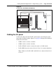
4 Connect LAN 1 (Ethernet) on the CP PIV faceplate to J31 (top) of the I/O
panel with cable NT4N90BA.
This connection can only be made after the Dual Ethernet Adapter is
installed (see step 3 above).
Note: If a LAN switch is not used, connect LAN 1 in Core 0 to LAN 1 in
Core 1.
5 Connect a crossover Ethernet cable (NTRC17BA) from the LAN 2 port in
Core 0 to the LAN 2 port Core 1. This connection is for Core redundancy.
Note: To ensure EMI shielding, route the cable along the front of the card
cage and through the sides of the Core/Net modules.
6 Repeat steps 1 through 4 in the second Core/Net module.
End of Procedure
CAUTION
Loss of Data
Label all cables on both ends before installation.
Labels help ensure that the cables are properly
routed and connected. Cable labels also help
installers to troubleshoot problems and replace
equipment.