
Communication Server Large System Installation and Commissioning


Cabling Common Equipment in a Single Group system Page 199 of 456
Communication Server 1000M and Meridian 1 Large System Installation and Commissioning
Procedure 25
Connecting the Clock Controller cables
See Figure 84 on page 205.
1 Connect P1 of the NT8D75 cable to port J3 of Clock Controller 0.
2 Connect P2 of the NT8D75 cable to port J3 of Clock Controller 1.
End of Procedure
Network Group 0: Shelf 0 to Shelf 1
Each Single Group System contains one Network group, Group 0. Each
Network group is comprised of two Network shelves: Shelf 0 and Shelf 1.
The Core/Net modules contain Network Group 0. Shelf 0 is in Core/Net 0,
Shelf 1 is in Core/Net 1. Shelf 0 must be connected to Shelf 1 for Network
Group 0 to operate correctly.
This section contains instructions on:
1 “Connecting the 3PE faceplates in the Core/Net modules” on page 199
2 “Inspecting CNI to 3PE factory installed cables” on page 200
3 “Connecting the Core/Net backplanes” on page 202
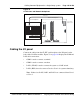
Connecting the 3PE faceplates in the Core/Net modules
The 3PE cards in the Core/Net modules must be directly connected with an
NT8D80 cable. See Figure 81 on page 201. This connection is only made
between the Group 0 shelves in the Core/Net modules.