
Communication Server Large System Installation and Commissioning


Cabling Common Equipment in a Single Group system Page 205 of 456
Communication Server 1000M and Meridian 1 Large System Installation and Commissioning
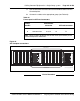
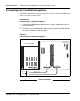
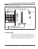
Figure 84
CP PIV to I/O panel connections
Procedure 29
Connecting the Core module to a LAN
1 Label both sides of two customer supplied Ethernet cables.
2 Connect a CAT5 Ethernet cable from J31 (top) on the Core/Net 0 I/O
panel to the LAN switch.
3 Connect a second CAT5 Ethernet cable from J31 (top) on the Core/Net 1
I/O panel to the LAN switch.
Enb
Dis
SYS
UTIL
USB
INIT
RESET
COM 2
cCNI
A
B
Enb
Dis
COM 1
CP
PIV
Core
c9 c10 c11 c12 c13 c14 c15 CP
NTRC17BA
(core to core)
J20J21J22J23
J24
J25
J26J27
J28
J29
J30
J31
J33J34
J35
J36
J37J38
553-9466
NT4N90BA (LAN switch)
NT4N88BA (modem)
NT4N88AA (terminal)
LAN 1
1
2
I/O Panel
(rear of module)
Core shelf (front of module)
NTRE40AA
Ethernet Adapter
LAN 1
LAN 2