
Communication Server Large System Installation and Commissioning


Cabling Common Equipment in a Multi Group system Page 215 of 456
Communication Server 1000M and Meridian 1 Large System Installation and Commissioning
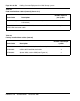
Optioning the System Utility Card
To install the system utility card, first identify Core/Net 0 and Core/Net 1
shelves. Then adjust the DIP switches according to Table 27 below.
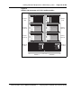
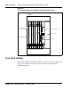
Figure 88 on page 216 shows Core card (front side) placement. If the Core
cards are not installed, refer to this figure to add or replace cards.
Table 27
System Utility Card DIP switch settings
Core/Net 0 Core/Net 1
DIP switch 1 on off
DIP switch 2 on on