
Communication Server Large System Installation and Commissioning


Page 242 of 456 Cabling network modules and loops
NN43021-310 Standard 02.01 December 2007
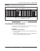
Figure 103
Network Group 0: Shelf 0 to Shelf 1 backplane connections
End of Procedure
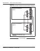
Connecting Groups 1 through 7: Shelf 0 to Shelf 1
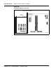
On the back of each Network module backplane are five connectors: A, B, C,
D and E. See Figure 104 on page 244. The connectors from Shelf 0 of each
Network Group 1 through 7 must be connected to the connectors in Shelf 1
of the same Network group.
Note: In North American systems, these connections are made in the
factory. In shipments outside North America, the Network shelves are
shipped separately. These connections must be made in the field.
553-9473
NT8D99AD cable
Network backplane
Core backplane
ED
E
D
NT8D99AD cable
To other
Core/Net
System Monitor
(XSM) connections
J1J2
J3
AB
j3 slot 9 port 0 j4 slot 9 port 0
Group 0
Group 1Group 2
Group 3Group 4Group 5
Group 6
Group 7
j3
slot 9
port 1
j4
slot 9
port 1
j3
slot 10
port 0
j4
slot 10
port 0
j3
slot 10
port 1
j4
slot 10
port 1
j3
slot 11
port 0
j4
slot 11
port 0
j3
slot 11
port 1
j4
slot 11
port 1
j3
slot 12
port 0
j4
slot 12
port 0
j3
slot 12
port 1
j4
slot 12
port 1
NT4N89 cable
NT4N29 cable
NT4N29 cable