
Communication Server Large System Installation and Commissioning


Cabling network modules and loops Page 253 of 456
Communication Server 1000M and Meridian 1 Large System Installation and Commissioning
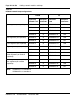
3 Cable network loops from the faceplate connector on the superloop
network card to the backplane for associated controller cards (see
Table 33 on page 254).
• Label both ends of an NT8D91 cable with the loop number, then
connect one end of the cable to the superloop network card faceplate
connector:
—J1 for Shelf1
—J2 for Shelf0
• On the backplane for the controller card, connect the cable to the
SL0, SL1, SL2, or SL3 connector assigned to the loop.
Note: The key (polarizing tab) on the side of the cable connector must be
inserted into the keyway on the left side, facing the backplane, of the
backplane connector. Blue and white wires should show through the top
of the cable connector and, if there is a directional label, the arrow on the
cable connector should be located at the top right.
Figure 110 on page 255 shows the superloop network card faceplate
connectors, the backplane connectors for the controller card, and the
cables required.
4 Seat and secure all connectors.
5 Set the Enb/Dis switch on each network card to Enb.
6 During system software configuration, use the Software Input/Output:
Administration (NN43001-611) to enter loop assignments.
End of Procedure