
Communication Server Large System Installation and Commissioning


Cabling lines and trunks Page 271 of 456
Communication Server 1000M and Meridian 1 Large System Installation and Commissioning
3T/3R
E/M
38/13
40/15
BK-G/G-BK
BK-S/S-BK
3
Note: Each of the following I/O panel connectors is cabled as shown
above: connectors A, B, C, D, E, F, G, H, K, L, M, N, R, S, T, and U. These
connectors are associated with backplane slots 0 through 15, sequentially.
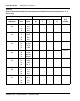
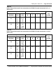
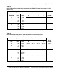
Table 40
NT8D37 IPE Module: NT8D15 E&M Trunk Card 4-wire type 1 and type 2 mode
pair-terminations (Part 1 of 2)
Lead designations
Pin numbers Pair color UnitType 1 Type 2
TA/ TB
RA/RB
E/M
ESC/ESCG
TA/ TB
RA/RB
EA/EB
MA/MB
26/1
27/2
28/3
29/4
W-BL/BL-W
W-O/O-W
W-G/G-W
W-BR/BR-W
0
TA/ TB
RA/RB
E/M
ESC/ESCG
TA/ TB
RA/RB
EA/EB
MA/MB
30/5
31/6
32/7
33/8
W-S/S-W
R-BL/BL-R
R-O/O-R
R-G/G-R
1
TA/ TB
RA/RB
E/M
ESC/ESCG
TA/ TB
RA/RB
EA/EB
MA/MB
34/9
35/10
36/11
37/12
R-BR/BR-R
R-S/S-R
BK-BL/BL-BK
BK-O/O-BK
2
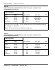
Table 39
NT8D37 IPE Module: NT8D15 E&M Trunk Card 2-wire type 1 mode
pair-terminations (Part 2 of 2)
Pair Pin numbers Pair color Unit