
Communication Server Large System Installation and Commissioning


Adding a module to a column Page 381 of 456
Communication Server 1000M and Meridian 1 Large System Installation and Commissioning
7 Install the perforated panel and top cap on the module being added:
a. Position the perforated panel and slide it slightly to the right (at the
rear). Install the screw that secures the panel and LED bracket.
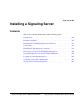
b. Position wiring from the perforated panel so it rests in the cable well
located next to the orange power connector at the rear of the module
(see Figure 137 on page 381).
Figure 137
Cable well location
c. Position the top cap and install the bolts that secure it.
d. Replace the air exhaust grills at the front and rear of the top cap.
8 Reconnect power to the top cap:
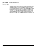
a. Connect the system monitor cable to J2 on the backplane. Line up
the alignment tab on the connector and snap on the pin headers to
position the connector correctly (see Figure 138 on page 381).
Figure 138
Monitor cable J2 backplane alignment tab and key alignment
Bracket
553-5889
Cable well
Top of
module
Orange connector
View at rear of module
Side view of connectors
Alignment tab
on backplane
connector
553-5885
Key on cable
connector