
Communication Server Large System Installation and Commissioning


Page 420 of 456 Installing a Signaling Server
NN43021-310 Standard 02.01 December 2007
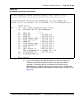
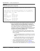
Figure 165
Stand-alone Signaling Server configuration
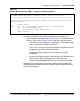
14 Enter the data networking and IP telephony parameters for the Signaling
Server, as prompted. The IP information applies to a temporary IP
Telephony node, to ensure that the existing node is not affected. The
entry of data networking and IP telephony parameters also preconfigures
the IP Telephony node files. After the Signaling Server software
installation, the node files are imported into Element Manager for further
configuration (see "Importing IP Telephony nodes" in Signaling Server:
Installation and Commissioning (NN43001-312)).
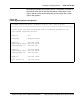
• If this is a Leader Signaling Server, enter the parameters for the
Node, ELAN network interface, TLAN network interface, and Call
Server as required.
— If installing the Signaling Server at an office that is not a branch
office, enter the ELAN network interface IP address of the Call
Server.
— If installing the Signaling Server at a branch office, enter the
ELAN network interface IP address of the MG 1000B Core.
• If this is a Follower Signaling Server, enter the Hostname of the
Leader Signaling Server. Then go to step 16 on page 423.
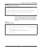
• If this is a stand-alone Signaling Server and not associated with a
Call Server (that is, b was selected in step 11 on page 416), enter the
CS 1000 Signaling Server Software Install Tool (sse-x.xx.xx)
=====================================================================
Please define the data networking parameters for this Standalone
Signaling Server. Note that the ELAN parameters are necessary for
Hostname : SS_SA
TLAN IP : 192.168.20.20
TLAN subnet mask: 255.255.255.0
TLAN gateway IP : 192.168.20.1
management access (e.g. SNMP).
ELAN IP : 192.168.10.20
ELAN subnet mask: 255.255.255.0
ELAN gateway IP : 192.168.10.1