
Switch User Manual


Using the BayStack 410-24T 10BASE-T Switch
2-18
309985-C Rev 00
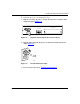
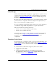
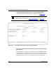
Figure 2-13. Main Menu for Standalone Switch
3.
Select IP Configuration/Setup (or press i) from the Main Menu.
This selection displays the IP Configuration/Setup screen (Figure 2-14
).
Note:
The default management VLAN (IP interface) for the BayStack
410-24T switch is VLAN 1. However, you can specify which VLAN you want
to be the management VLAN (see “
VLAN Configuration” on page 3-41).
Note:
IP addresses are written as four decimal numbers (for example,
123.123.123.123). Each decimal number represents an 8-bit octet. When
strung together, the four octets form the 32-bit Internet address. This is called
dotted-decimal notation. The largest possible value of a field in a
dotted-decimal number is 255, which represents an octet of all ones.
BayStack 410-24T Main Menu
IP Configuration/Setup...
SNMP Configuration...
System Characteristics...
Switch Configuration...
Console/Comm Port Configuration...
Display Hardware Units...
Spanning Tree Configuration...
TELNET/SNMP Mgr List Configuration...
Software Download...
Configuration File...
Display Event Log
Save Current Settings
Reset
Reset to Default Settings
Logout
Use arrow keys to highlight option, press <Return> or <Enter> to select option.