Title page Nortel Application Gateway 2000 Nortel Application Gateway Release 6.2 Hardware Installation Guide Installation Document Number: NN42360-303 Document Release: Standard 02.01 Date: January 2008 Year Publish FCC TM Copyright © 2008 Nortel Networks. All Rights Reserved.
Contents Preface v Audience v Organization v Conventions vi Related Documentation vi Online Documentation vii CHAPTER 1 Application Gateway Overview 1 Power 2 Connectors 3 Front Controls, LEDs, and CD Drive 3 Back Connectors 5 Rear LEDs 6 Specifications, Safety, and Other Information 6 CHAPTER 2 Hardware Installation and Initial Configuration 7 Readiness Checklist 7 Materials Required 8 Rack Mounting 9 Connecting and Powering up the Application Gateway 9 Alternate Procedure if Using a Crossover Ca
Contents iv Application Gateway Hardware Installation Guide
Preface This preface describes who should read the Application Gateway Hardware Installation Guide, how it is organized, and its document conventions. Audience This installation guide is intended for service technicians who will install the Application Gateway 2000. Organization This guide is organized as follows: Chapter Title Description Chapter 1 Application Gateway Overview Describes the server and its connectors.
Conventions Conventions This guide uses the following conventions: Convention Description boldface font Commands and HTML element names are in boldface. boldface screen Information you must enter is in boldface screen font. font Notes use the following conventions: Note Means reader take note. Notes contain helpful suggestions or other important information. Tips use the following conventions: Tip Means the following information will help you solve a problem.
Online Documentation Online Documentation To access Nortel documentation online, click the Technical Documentation link under Support on the Nortel home page: http://www.nortel.
Online Documentation viii Application Gateway Hardware Installation Guide
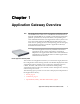
Chapter 1 Application Gateway Overview Note The Application Gateway 2000 is an appliance containing software and an IBM xSeries 306m server. The IBM documentation that is shipped with the IBM server includes rack mounting instructions, physical specifications, safety information, and operating and environmental information.
Chapter 1 Power Application Gateway Overview Power The power cord connector is located on the left side on the back of the Application Gateway. When the power LED, on the front panel, is illuminated, the power is on.The power control button is on the front panel. The power supplies are factory installed and not customer replaceable. Attention: This server is suitable for use on an IT power distribution system, whose maximum phase to phase voltage is 240 V under any distribution fault condition.
Chapter 1 Application Gateway Overview Connectors Connectors The following topics describe the Application Gateway connectors: • Front Controls, LEDs, and CD Drive, page 3 • Back Connectors, page 5 Front Controls, LEDs, and CD Drive Figure 1 shows the front of the Application Gateway. Figure 1 Application Gateway Front Controls, LEDs, and CD Drive Power-on LED: When this LED is lit, it indicates that the server is turned on.
Chapter 1 Application Gateway Overview Connectors Reset button: Press this button to reset the server and run the power-on self-test (POST). You might have to use a pen or the end of a straightened paper clip to press the button. Hard disk drive activity LED: When this LED is flashing, it indicates that a hard disk drive is in use. Locator LED: When this LED is lit, it has been lit remotely by the system administrator to aid in visually locating the server.
Chapter 1 Application Gateway Overview Connectors Back Connectors Figure 2 shows the back of the Application Gateway. Figure 2 Connectors on the back of the Application Gateway Power-cord connector: Connect the power cord to this connector. Serial connector: The DB-9 serial port is used to connect the Application Gateway to a computer that is capable of running terminal emulation software. This connection is used to access the Application Gateway Serial Console during initial configuration.
Chapter 1 Application Gateway Overview Specifications, Safety, and Other Information Rear LEDs Figure 3 shows the LEDs on the back of the Application Gateway. Figure 3 LEDs on the back of the Application Gateway Ethernet transmit/receive activity LED: This LED is on each Ethernet connector. When this LED is lit, it indicates that there is activity between the server and the network. Ethernet speed LED: This LED is on each Ethernet connector.
Chapter 2 Hardware Installation and Initial Configuration The following topics describe how to connect the Nortel Application Gateway 2000 to the network and perform initial configuration: • Readiness Checklist, page 7 • Materials Required, page 8 • Rack Mounting, page 9 • Connecting and Powering up the Application Gateway, page 9 • Licensing, page 15 Readiness Checklist Before starting the installation, complete the checklist in Table 1.
Chapter 2 Hardware Installation and Initial Configuration Materials Required Table 1 Readiness checklist (Sheet 2 of 2) Have you: ✓ Obtained the following: • screwdrivers • an ECOS 1023 POW-R-MATE or similar type of multimeter • appropriate cable terminating tools • a computer to be connected directly to the Application Gateway by a DTE—DTE null modem cable, with a teletype terminal (ANSI-W emulation, serial port, 19 200 bps) for the Application Gateway. Alternatively, a crossover cable and PC.
Chapter 2 Hardware Installation and Initial Configuration Rack Mounting You will need one network cable to connect the Application Gateway to a LAN or two cables if the Application Gateway will straddle two networks. Rack Mounting Refer to the IBM Rack Installation Instructions provided with the server.
Chapter 2 Hardware Installation and Initial Configuration Connecting and Powering up the Application Gateway • If the Application Gateway can access the connected device (router, application server, etc.) from the same subnet as it receives client requests, use one network cable. Connect Application Gateway interface port 0 (ethernet 2) to your network. This is the typical configuration.
Chapter 2 Hardware Installation and Initial Configuration Connecting and Powering up the Application Gateway b. Set the COM port on the maintenance terminal as follows: Note 3 • Terminal type: VT100 • Speed: 19200 • Data bits: 8 • Parity: none • Stop bits: 1 • Flow control: hardware The Application Gateway is shipped with the Admin/Serial port set to 19200 Bit/s. Connect the Application Gateway power cord. a.
Chapter 2 Hardware Installation and Initial Configuration Connecting and Powering up the Application Gateway To configure the Application Gateway using a serial console: 1 In the Application Gateway serial console, enter the default login root and the default password rootadmin. 2 Type 0 and press Enter to choose Express Setup. 3 Enter the IP address and netmask for Interface 0 when prompted. Note 4 The Application Gateway does not work with Dynamic Host Configuration Protocol (DHCP).
Chapter 2 Hardware Installation and Initial Configuration Connecting and Powering up the Application Gateway Alternate Procedure if Using a Crossover Cable If you prefer to use the Web-based Administration Tool rather than a serial console to change the network settings of the Application Gateway, follow the procedure described in this topic. You can use this procedure to perform the initial installation or to change the network settings after installation is completed.
Chapter 2 Hardware Installation and Initial Configuration Connecting and Powering up the Application Gateway 6 f. Enter the Subnet Mask 255.255.0.0. g. Enter the Default Gateway and click OK twice. Change the Application Gateway network settings: a. From a web browser on the connected PC, enter https://10.20.30.40:9001 to access the Application Gateway Administration Tool. b. If a Security Alert dialog box appears, click Yes. c.
Chapter 2 Figure 6 9 Hardware Installation and Initial Configuration Licensing Ethernet Port Connectors Remove the CD-ROM and restart the Application Gateway. 10 Install licenses as described in “Installing Licenses,” page 16. Refer to the Application Gateway Administration Guide for additional operating information. You can download all documentation from the Application Gateway Administration Tool.
Chapter 2 Licensing Hardware Installation and Initial Configuration Once you have logged into the KRS you will need the following information in order to produce your keycode license: • The MAC address of the server you want to license (i.e. 00:00:00:00:00:00 ) • The Purchase Order number or Nortel Order number (this is so you can locate your order which will list the software licensing items ordered). After logging into the KRS you will perform the following steps to generate your keycode license.
Chapter 2 3 Hardware Installation and Initial Configuration Licensing Click Open and then click Upload. You will be prompted to reboot. You do not have to reboot until you have uploaded all license files. When you save the Application Gateway configuration (Administration > Maintenance), license information is included in the backup file. To view the number of available licenses: • Note In the Administration Tool, go to the Administration > Licenses page.
Chapter 2 Licensing 18 Hardware Installation and Initial Configuration Application Gateway Hardware Installation Guide
Family Product Manual Contacts Copyright FCC notice Trademarks Document number Product release Document release Date Publish Nortel Application Gateway 2000 Hardware Installation Guide Installation Copyright © 2008 Nortel Networks. All Rights Reserved. LEGAL NOTICE While the information in this document is believed to be accurate and reliable, except as otherwise expressly agreed to in writing NORTEL PROVIDES THIS DOCUMENT "AS IS" WITHOUT WARRANTY OR CONDITION OF ANY KIND, EITHER EXPRESS OR IMPLIED.